Nortec LINKS 2 SETC B+ User Manual
Page 7
3 | Links 2 Retrofit for GSTC / SETC B+, NHTC, NHRS
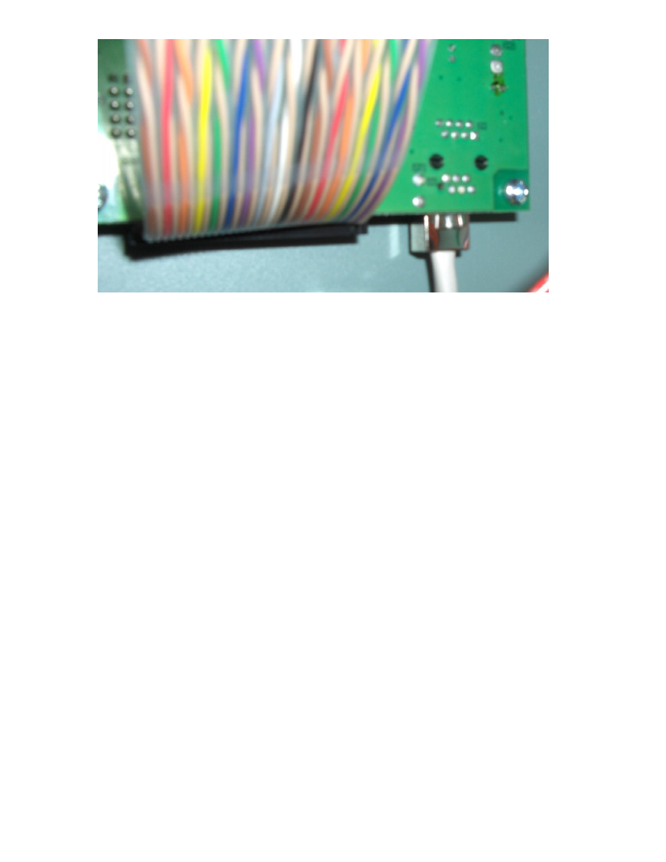
Figure 3: Rear of PCB
2 Connect power to the 24VAC and GND terminals of the LINKS 2 terminal strip. This may be
done in one of two ways:
a A 120VAC to 24VAC plug-in transformer with screw terminals on the secondary side has
been supplied with this kit. Wire the transformer to the 24VAC and GND terminals on the
Links 2 terminal strip.
b Connect power from the humidifier terminal strip (see wiring diagram for details). Power
to Links 2 module will be lost when the humidifier is switched off.
3 Connect the slave humidifiers (if applicable) to the Nortec Links Module. A twisted pair cable
should be used so that the Net + terminal on the Links module should connect to the first
pin (bottom-most pin) of the connector. The Net – terminal on the module should be
connected to the second pin of the connector. Refer to the unit’s wiring diagram for more
information.
Step 2 – Configuring the Humidifiers
Note: If the Links 2 remote package was shipped with the humidifiers, this step will have
already been performed by the factory.
1 Since Nortec Links 2 can connect to a maximum of 8 units, it will be necessary to set the
unit address for each humidifier. The lead unit can be determined by the presence of the
Links 2 module. The slave humidifiers can be given a unit address according to the number
the unit will have on the networked chain.
2 In order to change the current modbus address, press the Menu button on the keypad.
When prompted, enter the code 0335.
3 Once the password is set select the modbus address heading and press enter. Use the up
and down arrows to change the address setting.
4 Determine the desired humidifier ordering on the network. To change the network instance
follow step 3 and enter the parameter value of 2 for unit 2, 3 for unit 3 and so on.