OnLine Power PBC I User Manual
Page 12
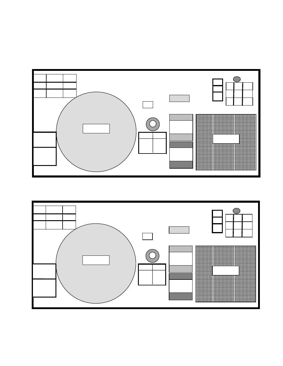
1–7 Other Important Design Features (continued)
• Electronic Tray
The inverter circuitry, front panel with connectors terminals and status panel, input and output isolation
transformers ( as well as power for heaters in 1300 W ) and cooling fans are all located on this mechanical
structure. (See Illustration 1- 3) Directly below for the front panel Illustration for an overview showing the
components layout. Details of the connectors are shown in section 3 for
electrical wiring of unit.
DOORS WITCH
Electronics Tray ( Upper Tray )
RED BLK
J3-1 J3-2
+ -
AC INV ALM LB HB FB LL HL FL OL
O O O OOOOOO OOOOOO
O 1 H1
O 2 H2
O 3 H3
OUT PUT
TB2
50HZ
60HZ
TB 3
O
3
X1
TB 1 INPUT
1
FREQ
SELECT
3
2
O
1
X1
O
2
X2N
B 3 FAN
B 2 FAN
O O
GROUND
LUG
DB 9
JACK
DOOR SW JACK
BATTERY JACK
ESD
CB 3
OUTPUT
CB 1
INPUT
Illustration 1-3
DOOR SWITCH
Electronics Tray ( Upper Tray ) IEC International Model
RED BLK
J3-1 J3-2
+ -
DB 9
JACK
CB 3
OUTPUT
CB 1
INPUT
B 2 FAN
AC INV ALM LB HB FB LL HL FL OL
O O O OOOOOO OOOOOO
O
3
L2
TB 1 INPUT
O
1
L1
O
2
B 3 FAN
O O
GROUND
LUG
DOOR SW JACK
ESD
BATTERY JACK
O 1 P1
O 2
O 3 P2
50HZ
60HZ
TB 3
1
FREQ
SELECT
3
2
TB2
OUT PUT
Illustration 1-3A
5