Caution – OnLine Power PBC I User Manual
Page 29
• Route the other 6 wires of cable to the punch down block are the correct length and attaches according to
your installation plan.
• Route the of DB-9 cable wires to the PDC Door Switch cable correct length to reach the punch down block
or Faston Terminal.
Ground
Cable
•
Route the Green wire up through the Gray Heyco fitting to the Ground lug on Electronic Tray.
• The torque shall be 45 lbs./Inch on Screw.
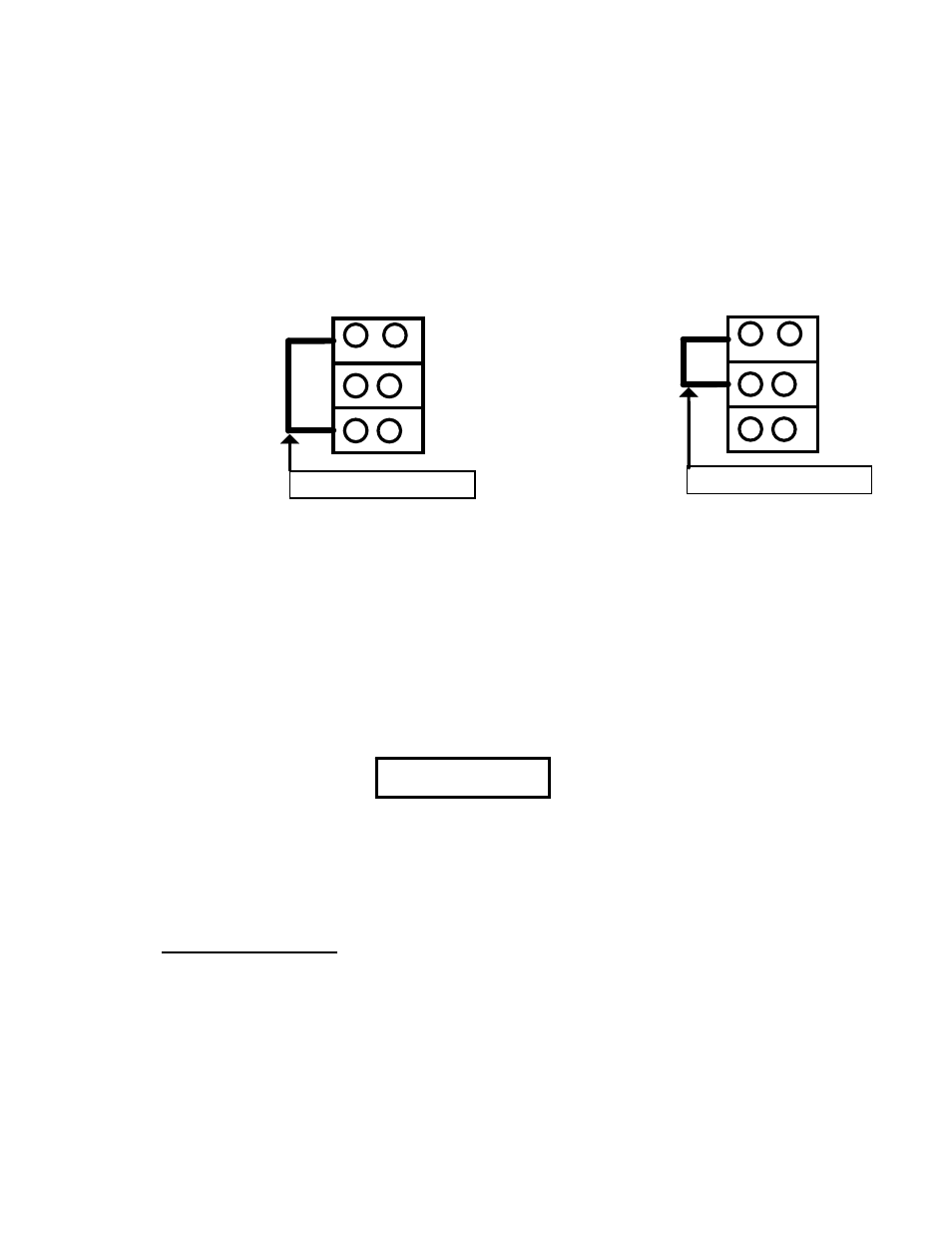
Frequency Selector Jumper
6
0
H
Z
JUMPER WIRING FOR 60 HZ
TB 3
5
0
6
0
H
Z
TB 3
5
0
RED JUMPER WIRE
JUMPER WIRING FOR 50 HZ
1
2
3
1
2
3
RED JUMPER WIRE
FREQUENCY JUMPER LOCATION
ILLUSTRATION 3 - 4
NOTE: FREQUENCY JUMPER ARE INSTALLED AT THE FACTORY AND
CAN BE CHANGED IN THE FIELD.
NOTE: FREQUENCY TB 3 SHOWN BELOW IS FOR LOCATION ONLY
DETAILS OF SETTING SHOWN ABOVE.
3-11 Electronic Tray, Input & Output Wiring
CAUTION !
Application of 240 VAC to the wrong terminals will cause
damage to the unit.
Green 8 awg wire from TB 3 - 2 to the ground lug is required by UL.
Wiring
Designation: Input
Output
L 1 - Hot line
L 1 - Hot line
L 2 - Hot line
L 2 - Hot line
N - Neutral
N - Neutral
Gnd-Ground
Gnd-Ground
22