Input, Caution, 3–9 pbc conduit installation – OnLine Power PBC I User Manual
Page 28: Cabinet conduit location, Output, Illustration 3 – 3, 10 electronic tray wiring - db-9 cable
CAUTION!!
: Make sure ALL POWER to PBC is Tagged Out & LOCK " OFF " Before working on
the Power Backup Cabinet Electrical System.
3–9 PBC Conduit Installation
• Install the Three, 3, Liquid-tight conduits, a Flexible cord, Plastic Liquid tight fitting (provided in the unit’s
accessory kit) into the bottom of the cabinet.
• Make sure the Liquid tight Seal ring is on the conduit fitting, then install it through the hole in bottom of
cabinet and add the Lock-nut .
• Check to make sure that all lock nuts are tight and the Flex to fitting connectors are tight.
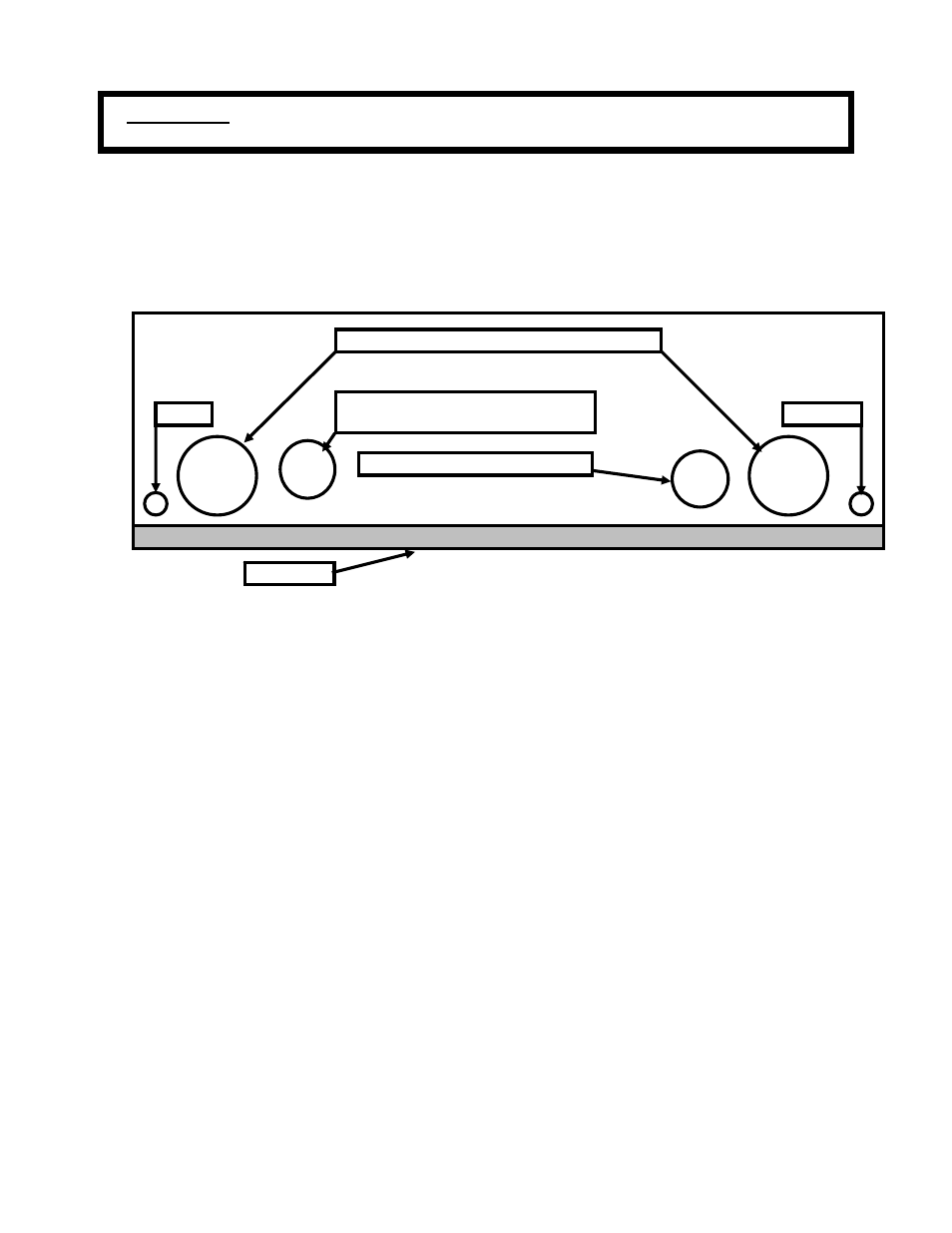
CABINET CONDUIT LOCATION
DB-9
GND
OUTPUT
INPUT
DOOR
DRAIN
DRAIN
3/4 Dia hole, Heyco Liquid Tight
Straight --Thru, Flexible Cord Fitting
1 inch, Liquid Tight Flexible Conduit
1 / 2 Inch, Liquid Tight Conduit
ILLUSTRATION 3 – 3
• See Illustration 3 - 3 for the fitting location.
• Install the wiring provided in the PBC Installation Accessory kit, as required according to your installation
plan.
3-10 Electronic Tray Wiring - DB-9 cable
• Connect the signal cable with the Male DB-9 to the DB–9 jack, female on the Electronic Tray.
• See Illustration 1- 3 for location of the DB-9 location on the front panel.
• Route the DB-9 signal cable TAGED END through the 1/2 inch conduit to the auxiliary cabinet.
• In the auxiliary cabinet strip the insulation back of the DB-9 cable and attaches according to your
installation plan.
• Route the Black of Black / Blue Wires of DB-9 cable to the PDC Door Switch cable, per your installation
plan.
• Attach the 1 Red Quick Disconnect, DV18-188B-C, to the Pin # 1 wire, Black of Black / Blue Wires, tagged
door open, attaches according to your installation plan to one side of the door switch.
• Attach the 1 Red Quick Disconnect, DV18-188B-C, to the Solid wire of the PDC Door Switch cable, Door
Open SW attaches according to your installation plan to the other side of the PDC Door Switch.
•
Route the Blue of Black / Blue Wires of DB-9 cable to the auxiliary cabinet punch down block, per your
installation plan.
21