OnLine Power PBC I User Manual
Page 34
3-16 PBC Unit is now ready for to Check Battery Back-up Operation.
•
Battery Tray shall be powered up for 24 to 48 hours before the battery back-up Operational Test.
•
After battery discharge, the batteries shall be recharged for 24 hours.
•
Turn “CB1" to the “ON” position and turn AC input breaker to “OFF ".
•
The Green “AC ON" LED shall go to “OFF” and the Green “INV ON" LED will stay “ON".
•
The “BATTERY LEVEL" shall LED’s will be “ ON “.
•
Turn AC input voltage “ON ". The Green “AC ON" LED shall go to “ON".
•
The Green “INV ON” LED will stay “ON". The Green “BATTERY LEVEL" shall stay “ ON “.
•
Turn CB 3 to “ON".
•
With a Digital Voltmeter check the output voltage.
•
Apply the load in steps. The Green “LOAD LEVEL" LED’s will light in succession as additional load
increases.
•
See Appendix C for battery evaluation.
3-17 The Backup Power Cabinet is ready for usage
.
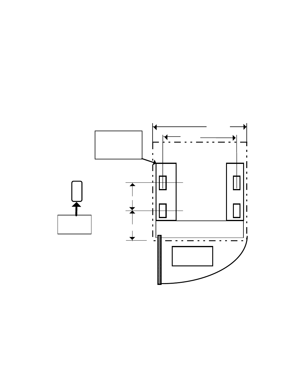
3-18 PBC Pad Layout.
• Use M12 or 1/2 inch Anchor Bolts for mounting
PAD Plate to Concrete Pad or Roof.
• PAD Plate may be crossways to door as shown.
3-19 PBC Pad Installation.
• Verify Center spacing of mounting bracket bolts are correct.
CONDUIT CONNECTION
AREA
17.00
19.50
4.00
12.00
PAD
MOUNTING
PLATE
4” W x 14” L x3” H
HOLE IS
5/ 8 x 1 1/4
O.D.
DOOR OPENING
120 DEGREE
ANGLE MAX
• Carefully lift the Cabinet into place on pad over the mounting bolts
• Verify Pad mounting brackets bolts have been torque to 165-inch lbs.
• Install the Conduits to the bottom of the Cabinet; follow directions in 3–9 and Illustration 3–3.
• Install the Cabinet to the Pad, and then use section 3–10 through 3–12 for electrical wiring.
• Check out the Electronic Tray wiring using Section 3-13 & Battery Tray connections per 3-14.
• PBC is ready for Normal operational Check out using Section 3-15 thru 3-17.
27