Start-up & commissioning, Technical guide vav/zone controller 12, Power wiring – Orion System VAV/Zone Controller User Manual
Page 12: Initialization, Vav/zone controller board, Figure 10: address switch setting
Technical Guide
VAV/Zone Controller
12
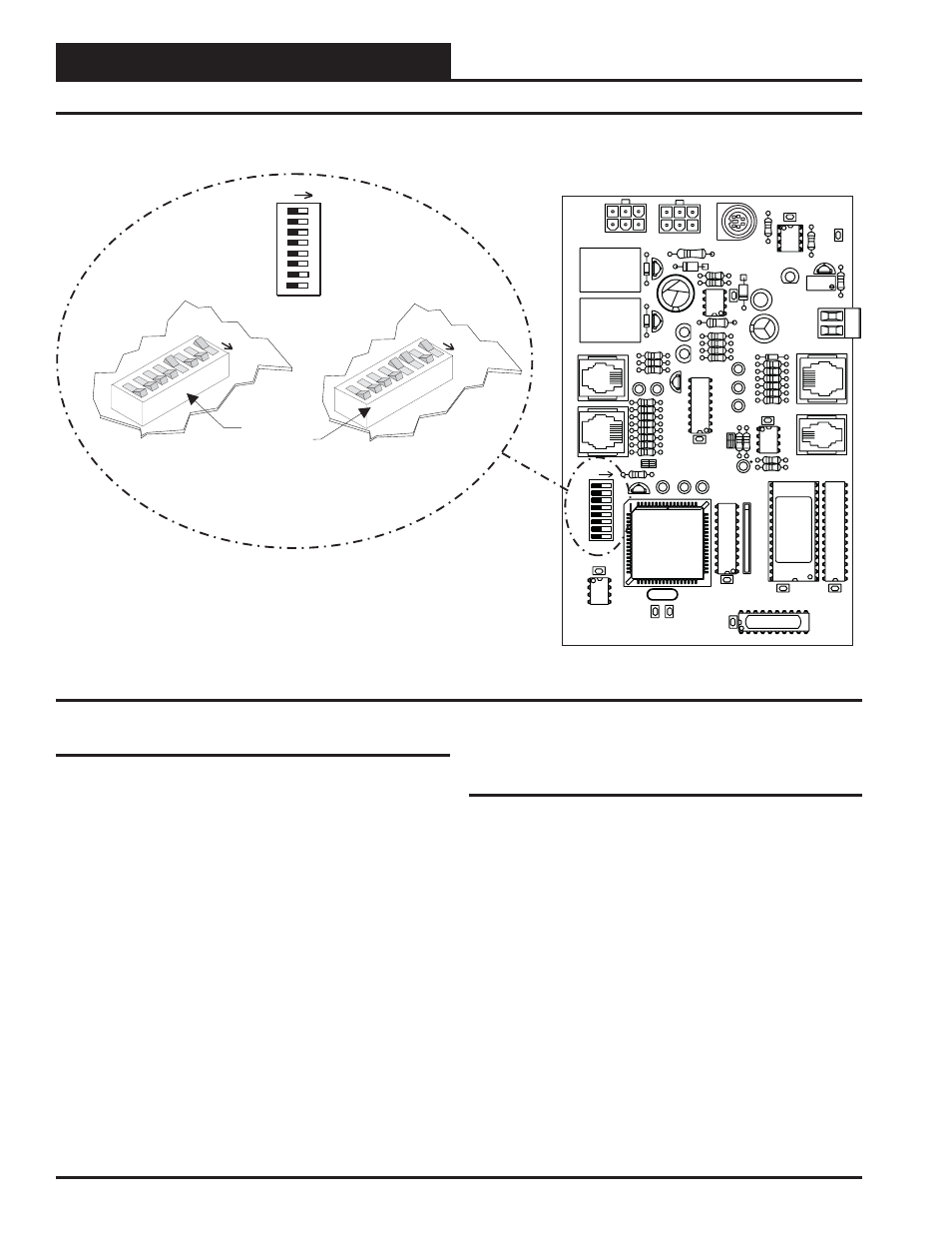
Figure 10: Address Switch Setting
VAV/Zone Controller Board
AC
TU
A
TO
R
EXP
AN
SIO
N
NET
ADD
8
32
16
2
4
1
SW1
U9
PJ4
AIR
FLO
W
SP
AC
E
SEN
SO
R
PJ3
R25
TB2
AIN
GND
P2
P1
PJ2
PJ1
16
32
NET
8
4
2
1
Address Switch Shown Is
Set For Address 9
Address Switch Shown Is
Set For Address 13
Controller
Address Switch
ADD
SW1
ADD
ADD
The Address For Each Controller
Must Be Between 1 And 58 And Be
Unique To The Other Controllers
On The Local Loop
Power Wiring
One of the most important checks to make before powering up the sys-
tem for the first time, is to confirm proper voltage and transformer
sizing for the Power/Comm board that is connected to it. Each VAV/
Zone controller requires 6 VA of power delivered to it at 24 VAC. See
pages 7 and 8 of this manual for complete wiring and transformer sizing
information for the VAV/Zone controller and its associated Power/Comm
board. All VAV/Zone controllers must be connected to a Power/Comm
board using prefabricated modular cables.
Check all modular connectors to be sure they are completely pushed
and locked into their mating connectors. Confirm that all sensors re-
quired for your system are mounted in the appropriate location and that
the modular cables are plugged into the correct connectors on the VAV/
Zone controller. Check the actuator cable and be sure it is plugged in
and secured to the modular connector on the actuator and the VAV/
Zone controller board modular connector. Check that the Modular Room
Sensor modular connector is connected to one end of the modular sen-
sor cable and the other end is connected to the modular sensor connec-
tor on the VAV/Zone controller board. Be sure any expansion boards
connected to the VAV/Zone controller are also correctly wired per the
expansion board wiring instructions on pages 7 through 12 of this manual.
After all the above wiring checks are complete, apply power to the
Power/Comm board that is connected to the VAV/CAV controller(s).
Initialization
Upon applying power to the VAV/Zone controller the following should
occur:
On system power-up, the SCAN LED is extinguished for a few seconds
and then the controller “flashes” its address switch setting. If the ad-
dress switch were set to 7, you would see 7 flashes. After the address is
finished, the LED will extinguish for another 5 seconds. At the conclu-
sion of this 5-second delay, the LED will begin a continuous flashing
while the Damper Feedback limits are calibrated. If the Damper is driv-
ing open, the LED will blink slowly. If the Damper is driving closed,
the LED will blink fast. When the calibration is completed, the normal
diagnostic flashes will commence. These diagnostic flashes are described
later in this document. In addition, during the first few seconds of power-
up, all default setpoints are initialized and all outputs are turned off.
There is also a 30 second start-up delay to protect the fan and other
components from short cycling during intermittent power conditions. If
all inputs are operating correctly it will blink once every ten seconds.
Start-up & Commissioning