Troubleshooting, Technical guide vav/zone controller 24 – Orion System VAV/Zone Controller User Manual
Page 24
Technical Guide
VAV/Zone Controller
24
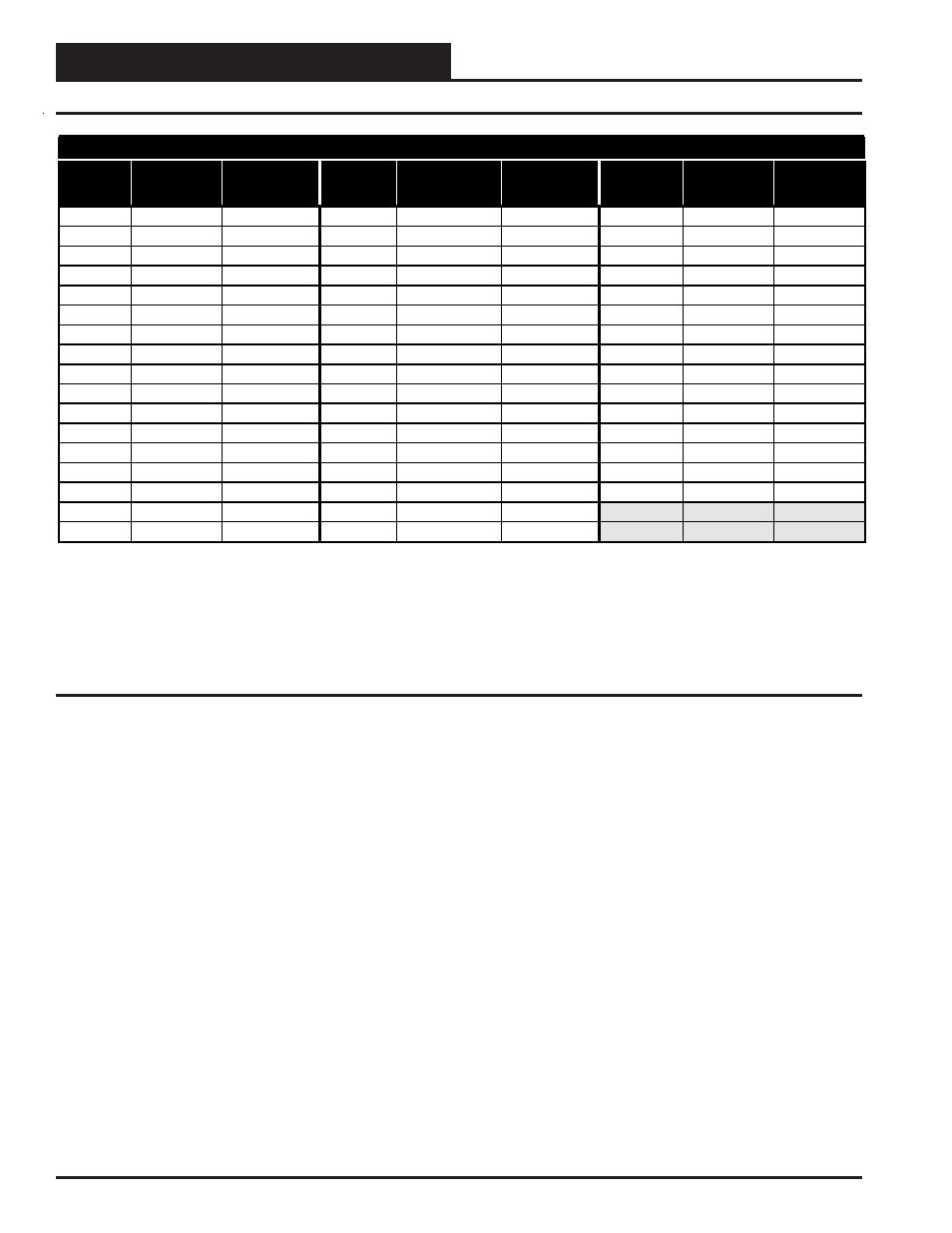
Temperature – Resistance – Voltage For Type III 10 K Ohm Thermistor Sensors
Temp
(ºF)
Resistance
(Ohms)
Voltage @
Input (VDC)
Temp
(ºF)
Resistance
(Ohms)
Voltage @
Input (VDC)
Temp
(ºF)
Resistance
(Ohms)
Voltage @
Input (VDC)
-10
93333 4.620 60 14681 3.042 86 8153 2.297
-5
80531 4.550 62 14014 2.985 88 7805 2.242
0 69822 4.474 64 13382 2.927 90 7472 2.187
5 60552 4.390 66 12758 2.867 95 6716 2.055
10
52500 4.297 68 12191 2.810 100 6047 1.927
15
45902 4.200 69 11906 2.780 105 5453 1.805
20
40147 4.095 70 11652 2.752 110 4923 1.687
25
35165 3.982 71 11379 2.722 115 4449 1.575
30
30805 3.862 72 11136 2.695 120 4030 1.469
35
27140 3.737 73 10878 2.665 125 3656 1.369
40
23874 3.605 74 10625 2.635 130 3317 1.274
45
21094 3.470 75 10398 2.607 135 3015 1.185
50
18655 3.330 76 10158 2.577 140 2743 1.101
52
17799 3.275 78 9711 2.520 145 2502 1.024
54
16956 3.217 80 9302 2.465 150 2288 0.952
56 16164 3.160 82
8893
2.407
58 15385 3.100 84
8514
2.352
Thermistor Sensor Testing Instructions
1.) Use the resistance column to check the thermistor sensor while disconnected from the controllers (not powered).
2.) Use the voltage column to check sensors while connected to powered controllers. Read voltage with meter set on DC volts. Place the “-”
(minus) lead on GND terminal and the “+”(plus) lead on the sensor input terminal being investigated.
If the voltage is above 5.08 VDC, then the sensor or wiring is “open.” If the voltage is less than 0.05 VDC, the sensor or wiring is shorted.
Table 6: Temperature Sensor - Voltage & Resistance for Type III Sensors
Troubleshooting