Controller installation & wiring, Controller inputs and outputs, Technical guide vav/zone controller 6 – Orion System VAV/Zone Controller User Manual
Page 6: General, Controller mounting, Important wiring considerations, Figure 4: vav/zone controller wiring
Technical Guide
VAV/Zone Controller
6
Notes:
1
0
Locate In Supply Duct
Near Zone Damper
Zone Actuator
Supply Air
Temperature
Sensor
VAV/Zone Controller Board
Room Sensor
(See Note 3)
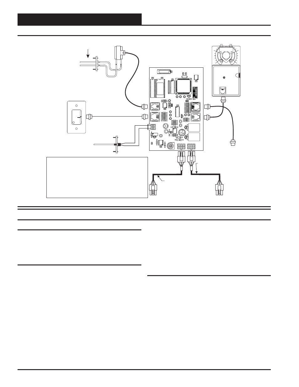
3.)The Supply Air Sensor is not required when the VAV/Zone Controller is
connected to an Orion VAV/CAV Unit Controller board. A global supply air
temperature is broadcast by the VAV/CAV Unit Controller. The Supply Air
Sensor is only required if the VAV/Zone Controller is required to operate as a
“Stand Alone” controller. It can also be used on VAV/Zone controllers that have
reheat to monitor the box discharge air temperature.
1.) All wiring to be in accordance with local and national electrical codes
and specifications.
2.) Use Orion prefabricated modular cables for connection between the
VAV/Zone controller, the Power/Comm Board and between each VAV/Zone
controller on the loop.
NORMAL
OVR
R
E
L
O
C
R
E
M
R
O
A
W
ACTUA
T
O
R
EXP
ANSION
NET
ADD
8
32
16
2
4
1
SW1
U9
PJ4
AIRFLOW
SP
ACE
S
ENSOR
PJ3
R25
TB2
AIN
GND
P2
P1
PJ2
PJ1
Hi
Lo
Airflow
Airflow Probe & Sensor
(For Pressure Independent Applications Only)
Power/Comm Cable To
Next VAV/Zone Controller or
Power/Comm Distribution Board
Power/Comm Cable
From Power/Comm Distribution Board
Or Previous VAV/Zone Controller
To Optional Relay
Expansion Board
Figure 4: VAV/Zone Controller Wiring
Controller Installation & Wiring
General
Correct wiring of the VAV/Zone controller is the most important factor
in the overall success of the controller installation process. The VAV/
Zone controller wiring has been simplified by the use of modular con-
nectors and prefabricated modular cables.
Controller Mounting
If the Round Zone Dampers or Rectangular Zone Damper Kits were
purchased from WattMaster, the controller and actuator are factory
mounted and wired in the damper control enclosure. If your VAV/Zone
controllers are pressure independent, an airflow probe and pressure sen-
sor will also be factory mounted and wired.
Most terminal unit manufacturers will offer the option of factory mount-
ing the Orion controls in their terminal units for an additional charge.
An installation worksheet and instructions are available for the Orion
VAV/Zone controller package which can be shipped with the VAV/Zone
control(s) to the terminal unit manufacturer to simplify third party fac-
tory mounting and wiring of the controller.
When the VAV/Zone controller is to be field mounted, it is important to
mount the controller in a location that is free from extreme high or low
temperatures, moisture, dust and dirt. The VAV/Zone controller board
must be mounted within 10” of the damper actuator in order for the
actuator cable to extend between the controller and the actuator.
Be careful not to damage the electronic components when mounting
the controller. Remove the controller from its snap track mount. Mark
the control enclosure base using the snap track as a template. Drill pilot
holes in the enclosure base and secure the snap track to it using sheet
metal screws. Do not allow metal shavings to fall onto the circuit board.
Reattach the controller to the snap track. Mount the damper actuator to
the damper shaft following the instructions supplied with the damper
actuator.
Important Wiring Considerations
Please carefully read and apply the following information when wiring
the VAV/CAV controller. See Figure 4 for VAV/Zone controller wiring
diagram.
1.
Size and wire the Power/Comm Board transformer per the
instructions. Failure to size the transformer and/or wire the
Power/Comm board correctly may cause the VAV/Zone
controllers to operate erratically or not at all. See
Figure 5 for wiring and transformer sizing information.
2.
If a Supply Air Sensor is to be connected, the minimum
wire size used should be 24 gauge.
3.
Do not pry on the connectors when connecting or
disconnecting the modular cables. Be sure to push in on the
connector release clip and then pull straight up.
Controller Inputs and Outputs