Controller inputs and outputs, Vav/zone controller technical guide 5, Vav/zone controller analog inputs – Orion System VAV/Zone Controller User Manual
Page 5: Other controller connections, Optional - oe322 expansion board
VAV/Zone Controller
Technical Guide
5
The following inputs and outputs are available on the VAV/Zone con-
troller and the OE322 Output Expansion Board that can be added by
connecting it to the main controller board expansion port. For compo-
nent locations of the inputs on the VAV/Zone Controller see Figure 3.
For wiring of inputs and outputs see Figure 4 thru 9.
VAV/Zone Controller Analog Inputs
Input #1: Space Temperature
The Modular Room Sensor that reads space temperature is attached to
this input. The Modular Sensor connects via a modular cable to the
VAV/Zone controller. If the optional push-button override sensor is in-
stalled, this input will detect user overrides from unoccupied back to
occupied operation for a user adjustable amount of time.
Input #2: Airflow Sensor
If the VAV/Zone Controller is to be configured for pressure indepen-
dent operation, you need to install the OE274 Airflow Sensor and con-
nect the modular plug from the pressure sensor to this input. The pres-
sure signal from the Airflow Sensor is used for CFM (airflow) calcula-
tions. If an OE274 Airflow Sensor is attached to this input, the VAV/
Zone controller will automatically detect this and switch to pressure
independent operation. If the sensor is not attached or becomes defec-
tive, the controller automatically reverts to pressure dependent opera-
tion. When the VAV/Zone controller is used for pressure independent
applications, the JP2 jumper must be “ON” for high velocity systems
and “OFF” for low velocity systems. Typically VAV systems are me-
dium to high velocity and voting systems are low velocity. As a rule of
thumb, if the velocity through the terminal unit is below 1500 FPM,
remove the jumper and if above 1500 FPM, leave the jumper on. If it is
a low velocity system, in addition to removing the jumper, the configu-
ration option: “Is This a Voting System” must be YES, even on a VAV
system. If the CFM is greater than the values listed for the terminal inlet
size above, the JP2 jumper on the VAV/Zone controller must be in-
stalled and the system must be configured as a “Non-Voting System. If
this is a high velocity voting system the box must be configured as a”
voting box” but the system must be configured as “non-voting system”
in order for the airflow sensor to read correctly. See Figure 3 for jumper
location on board. See Table 1 for low velocity inlet CFM informa-
tion.
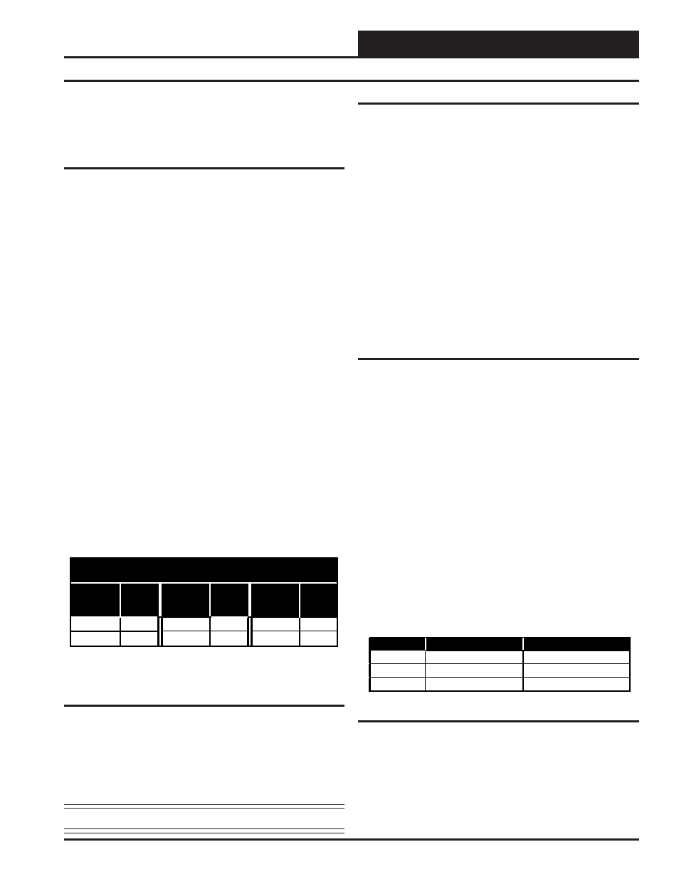
Maximum Inlet CFM for Low Velocity (1500 FPM)
JP2 Jumper Removed
Inlet
Size
Box
CFM
Inlet
Size
Box
CFM
Inlet
Size
Box
CFM
6”
Dia. 260 8”
Dia. 500 10”
Dia. 775
12” Dia.
1100
14” Dia.
1550
16” Dia.
2025
Notes:
1.) These values are averages and will vary between term inal unit
m anufacturers.
Table 1: Maximum Inlet CFM for Low Velocity
Input #3: Aux - Supply Air Temperature Sensor
A Supply Air Temperature Sensor can be connected to these terminals.
It should be mounted in the supply duct close to the terminal unit where
the VAV/Zone controller is installed. This sensor can be used for moni-
toring purposes or in place of the Supply Air Temperature Broadcast
from the VCM Controller.
Note: All temperature sensors must be Thermistor Type III.
Other Controller Connections
Expansion Board Modular Connector
This modular connector is used to connect the optional OE322 Output
Expansion Board to the VAV/Zone controller. These boards are only
required when electric or hot water heating and/or fan terminal control
is required. The expansion boards are not required for cooling only
terminal units.
Actuator Modular Connector
This modular connector is used to connect a modular cable from the
VAV/Zone controller to a tri-state actuator.
Power/Comm Modular Connectors
These two modular connectors, (labeled P1 & P2) are used to connect
modular cables from the Power/Comm board that supplies 24 Volt power
and communications to the controller and to supply 24 Volt power and
communications to the next controller on the local loop.
Modular Service Tool DIN Connector
This connector is used to connect a cable between the Modular Service
Tool and the VAV/Zone controller for programing and configuration of
the VAV/Zone controller.
Optional - OE322 Expansion Board
As previously stated when control of a fan or if heating is required the
OE322 Output Expansion board must be used.
Relay Output #1 - Fan Enable
The first expansion relay on the Output Expansion boards is used for
enabling the fan for Series or Parallel Fan Terminal Units.
Relay Output #2 - Stage 1 Heating
If you have at least one stage of auxiliary heating, this is the relay used
to energize the 1st stage of terminal unit heating. This heating stage can
either be used with electric heat or On/Off hot water valve control.
Relay Output #3 - Stage 2 Heating
If you have two stages of auxiliary heating, this relay controls the 2nd
stage of electric heat. For 3 stage heating, this relay output would be
energized for both the 2nd and 3rd stage of heat. See the following
section for more information regarding 3 stage heating applications.
3 Stage Heating Applications
If three stages of electric heat are configured, relays #2 and #3 will
stage in a staggered sequence. This allows you to achieve 3 stages of
heating using only relays #2 and #3. Each of the 3 heating elements
should be sized for 1/3 of the total KW output required. Both the 2nd
and 3rd stage heating contactors (C2 & C3) must be connected to Relay
Output #3. See Table 2 for relay sequencing information.
Stage N o.
R elay Output #2
R elay Output #3
#1
ON (C 1)
OF F (C 2 & C3)
#2
OFF (C1)
ON (C2 & C3)
#3
ON (C 1)
ON (C2 & C3)
Table 2: Relay Sequencing For 3 Stage Heating
24 VDC Power Terminals (+V & GND)
These terminals can supply 24 Volts DC for a 24 VDC hot water valve
actuator if desired. This output is rated at 12 Watts maximum load.
Analog Output
If you are using hot water or steam heating via a modulating steam or
hot water valve, this output can supply a 0-10 Volts DC signal for pro-
portional control of the valve.
Controller Inputs and Outputs