Hb mini controller technical guide 13 – Orion System HB Mini User Manual
Page 13
HB Mini Controller
Technical Guide
13
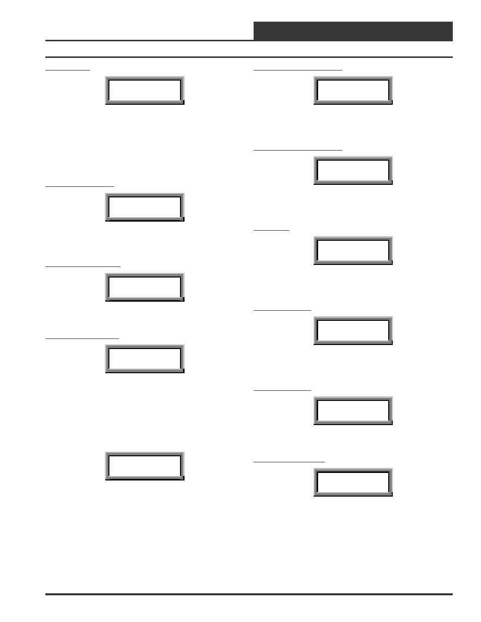
Reset Counts
Reset Count
XXXX
Line #2 displays the total number of times the HB Mini Controller has
been reset or has had its power cycled.
Fan Module Status Screens
The Fan Module Status Screens are accessed by navigating to the Fan
Module and pressing the ENTER key.
Fan Terminal Active
G-Active
NO
Line #2 displays “YES” if there is a 24 VAC signal connected to the
“G” Fan terminal on the HB Mini Controller.
High Speed Fan Relay
High Fan Relay
OFF
Line #2 displays “ON” if the High Speed Fan Relay is active.
Low Speed Fan Relay
Low Fan Relay
OFF
Line #2 displays “ON” if the Low Speed Fan Relay is active.
Cooling Module Status Screens
The Cooling Module Status Screens are accessed by navigating to the
Cooling Module screen and pressing the ENTER key. The following
screen will then appear.
Status
Setpoints
Select “Status” by pressing the ENTER key. Press the up or down SE-
LECT arrow key to move forward or backward through the Cooling
Module Status screens.
Cooling Stage 1 Energized
Y1-Active
NO
Line #2 displays “YES” if there is a 24 VAC signal on HB Mini Con-
troller terminal “Y1”.
Cooling Stage 2 Energized
Y2-Active
NO
Line #2 displays “YES” if there is a 24 VAC signal on HB Mini Con-
troller terminal “Y2”.
Fan Status
Fan Status
Fan Off
Line #2 displays the current Supply Fan Status. If the Supply Fan is
on, line #2 displays either “Fan Low Speed” or “Fan High Speed”.
Cooling Relay #1
Cool 1 Relay
OFF
Line #2 displays “ON” if Cooling Relay #1 is active.
Cooling Relay #2
Cool 2 Relay
OFF
Line #2 displays “ON” if Cooling Relay #2 is active.
Low Pressure Switch
LPS
OPEN
Line #2 displays the current status of the Low Pressure Switch. It will
only display “CLOSED” when Cooling Relay #1 relay is active and
the Low Pressure Switch is operating correctly.