Troubleshooting – Orion System HB Mini User Manual
Page 19
HB Mini Controller
Technical Guide
19
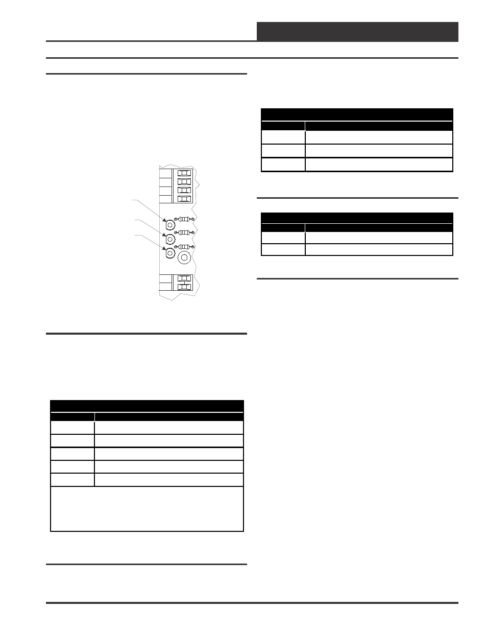
Using LEDs To Verify Operation
The HB Mini Controller is equipped with LEDs that can be used as
very powerful troubleshooting tools. The HB Mini Controller circuit
board has three different colored LEDs. See Figure 8 for the various
LED locations. The Red LED is used to indicate fault conditions. The
Yellow LED indicates the mode of operation the HB Mini Controller is
currently operating in. The Green LED indicates the power and com-
munications status of the HB Mini Controller.
LD3
LD2
LD1
GND
SAT
POS
GND
RAB
TB2
RESET
ECONO
MHGRV
TB1
LD1 - Red LED
HB Controller Board
LD2 - Yellow LED
LD3 - Green LED
Figure 8: HB Board LED Locations
One LED blink is defined as a 1 second LED on period immediately
followed by a 1 second LED off period. After each series of blinks is
completed the LED will power off for 3 seconds and then repeat the
series of blinks. The various blink codes and their meanings are defined
in the tables that follow.
Red LED
LED Blinks
Fault Condition Description
1
Heat Safety Lockout
2
High Pressure Fault
3
Low Pressure Lockout
5
Bad Outdoor Air Temperature Sensor
7
Clogged Filter Switch
Notes:
1.) When no fault exists the red LED will be off.
2.) Heat Safety Lockout (1 blink) is the highest priority. Clogged
Filter Switch (7 blinks) is the lowest priority.
Table 1: Red LED Blink Codes
HB Mini Controller Fault Condition Operation
If the Red LED indicates you have a Bad Outdoor Air Temperature
Sensor, heating mode will operate but Cooling Mode will be disabled
until the sensor problem is fixed.
Yellow LED
LED Blinks
Mode Indication Description
1
Vent Mode (Fan Only)
2
Heating Mode
3
Cooling Mode
Table 2: Yellow LED Blink Codes
Green LED
LED Blinks
Power/Communications Description
1
Power Indicator (No Communications)
2
HSS Communications
Table 3: Green LED Blink Codes
Troubleshooting