OWON ODP Series User Manual
Page 13
Advertising
4.Quick Start
8
Channel 1
Channel 2
(same layout as Channel 1)
①
④
② ③
⑧
⑩
⑨
⑦
⑥
⑤
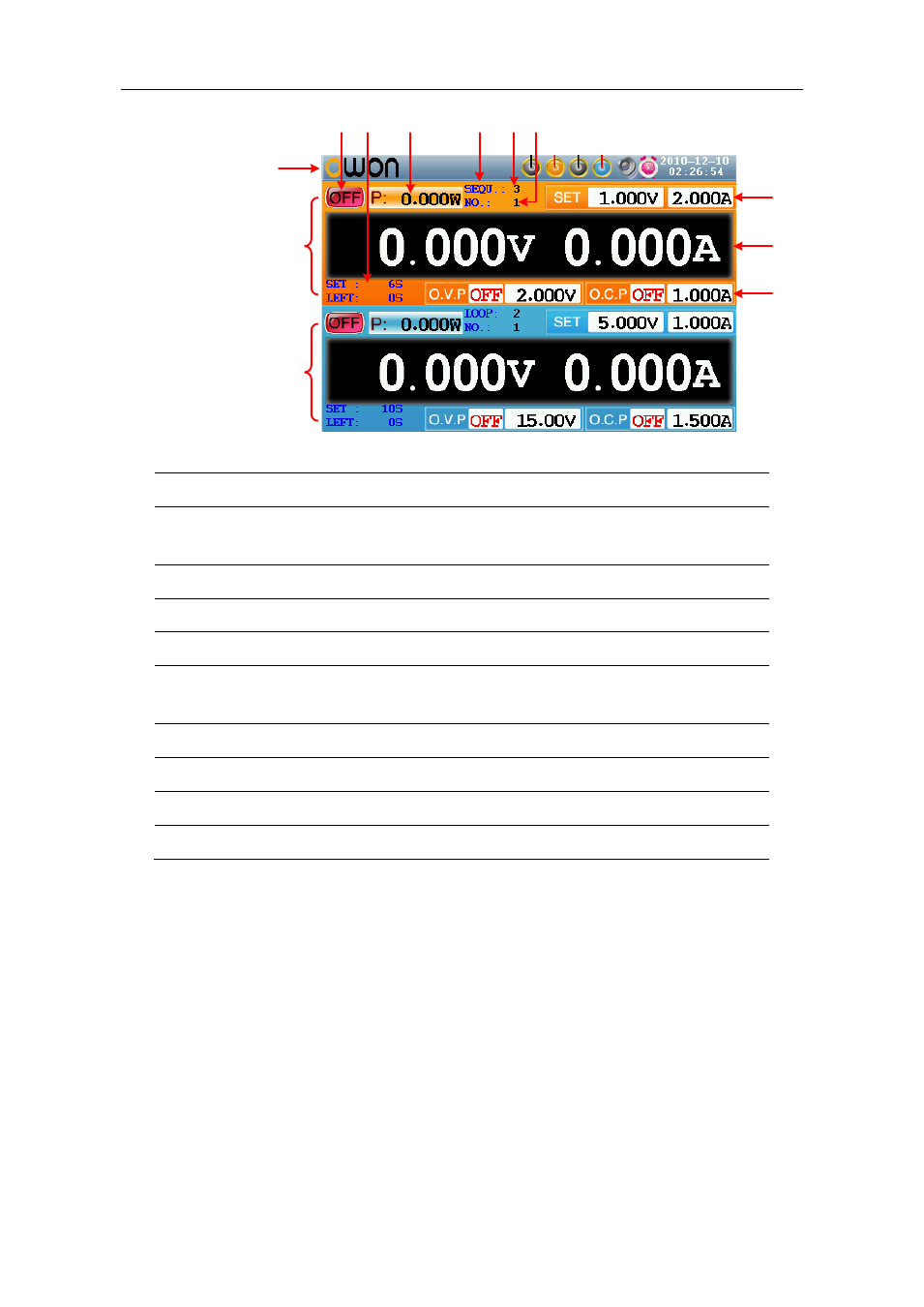
Figure 4-3 User interface in Independent mode
① Output status of Cannel 1
② Specified time and left time of current output when the timing output of
Channel 1 is on
③ Actual output value of power for Channel 1
④ Timing output mode of Channel 1 (Sequence / Loop)
⑤ Timer range of Channel 1
⑥ The parameter number of the current output when the timing output of
Channel 1 is on.
⑦ Set values of voltage and current for Channel 1
⑧ Actual output values of voltage and current for Channel 1
⑨ Status and set values of O.V.P and O.C.P for Channel 1 in current status
⑩ Status icons, see "Status Icons" on P10 for more details
Parallel /Series Mode
Advertising