2 power on, 4 output inspection, 1 voltage output inspection – OWON ODP Series User Manual
Page 17: 2 current output inspection
4.Quick Start
12
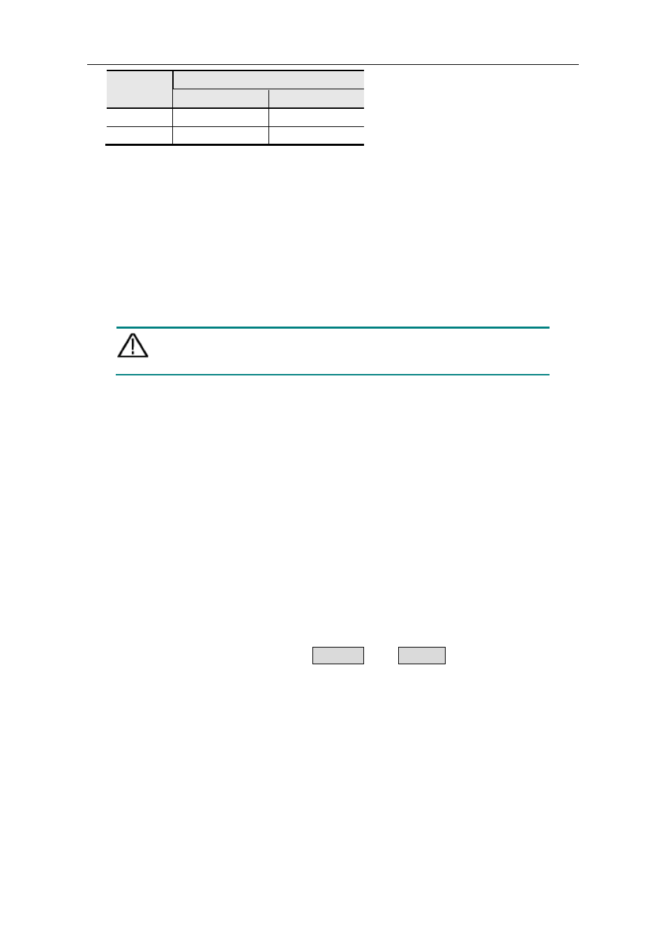
Voltage
Fuse
ODP3032
ODP3052
AC110V
125 V,F5 A
125 V,F10A
AC220V
250 V,F3 A
250 V,F5A
To change the input voltage scale of the instrument, do the following steps:
(1) Turn off the power button at the front panel and remove the power cord.
(2) Check if the fuse installed before leaving factory (250 V, F3 A) can match with the
selected voltage scale; if not, pry the cover open using a straight screwdriver (see ⑤
in Figure 4-2), change the fuse.
(3) Regulate the Power Switch to the right voltage scale.
4.3.2 Power On
(1) Connect the instrument to the AC supply using the supplied power cord.
Warning:
To avoid electric shock, the instrument must be grounded properly.
(2) Press down the power button at the front panel, the orange and blue key is lighted;
the screen shows the boot screen.
(3) Press any key to enter.
4.4 Output Inspection
Output inspection is to ensure that the instrument can achieve its rated outputs and
properly respond to operation from the front panel. For the procedures below, it is
suggested that you read "Working Mode" on P13, "Turn On/Off the Channel Output" on
P16 and "Set the Output Voltage/Current" on P16.
4.4.1 Voltage Output Inspection
The following steps verify basic voltage functions without load:
(1) When the instrument is under no load, power on it; make sure that the output current
setting value of each working mode is none-zero.
(2) Turn on the channel output. The ON/OFF and Volt/CV key is lighted, which
indicates the channel you opened is in Constant Voltage output mode.
(3) In each working mode, set some different voltage values; check if the actual voltage
value displayed is close to the set voltage value, and to check if the actual current
value displayed is nearly zero.
(4) Check that if the output voltage can be adjusted from zero to the maximum rating.
4.4.2 Current Output Inspection
The following steps check basic current functions with a short across the power supply's
output:
(1) Power on the instrument.
(2) Connect a short across (+) and (-) output terminals with an insulated test lead. Use a
wire size sufficient to handle the maximum current.