Posiflex IVA XT-3815 User Manual
Page 10
2. Second LCD Monitor
Before installing the rear top mount
upgrade kit, such as LM/TM-
3010/3014/3015 and PD-6607,
remove the 4 circled screws from
the rear top mount upgrade kit
cover located at the upper side of
the rear of main unit.
For the detailed description of installation of the rear top
mount upgrade kit, refer to the XT-3615/3815 technical
manual or the user manual of LM/TM-series peripheral
kit.
Note: When being installed with the LM/TM-
3014/3015-XT, the XT system must be provided with a
80W power adapter.
Routing and Securing the Cable of PD or 2
nd
LCD
Monitor
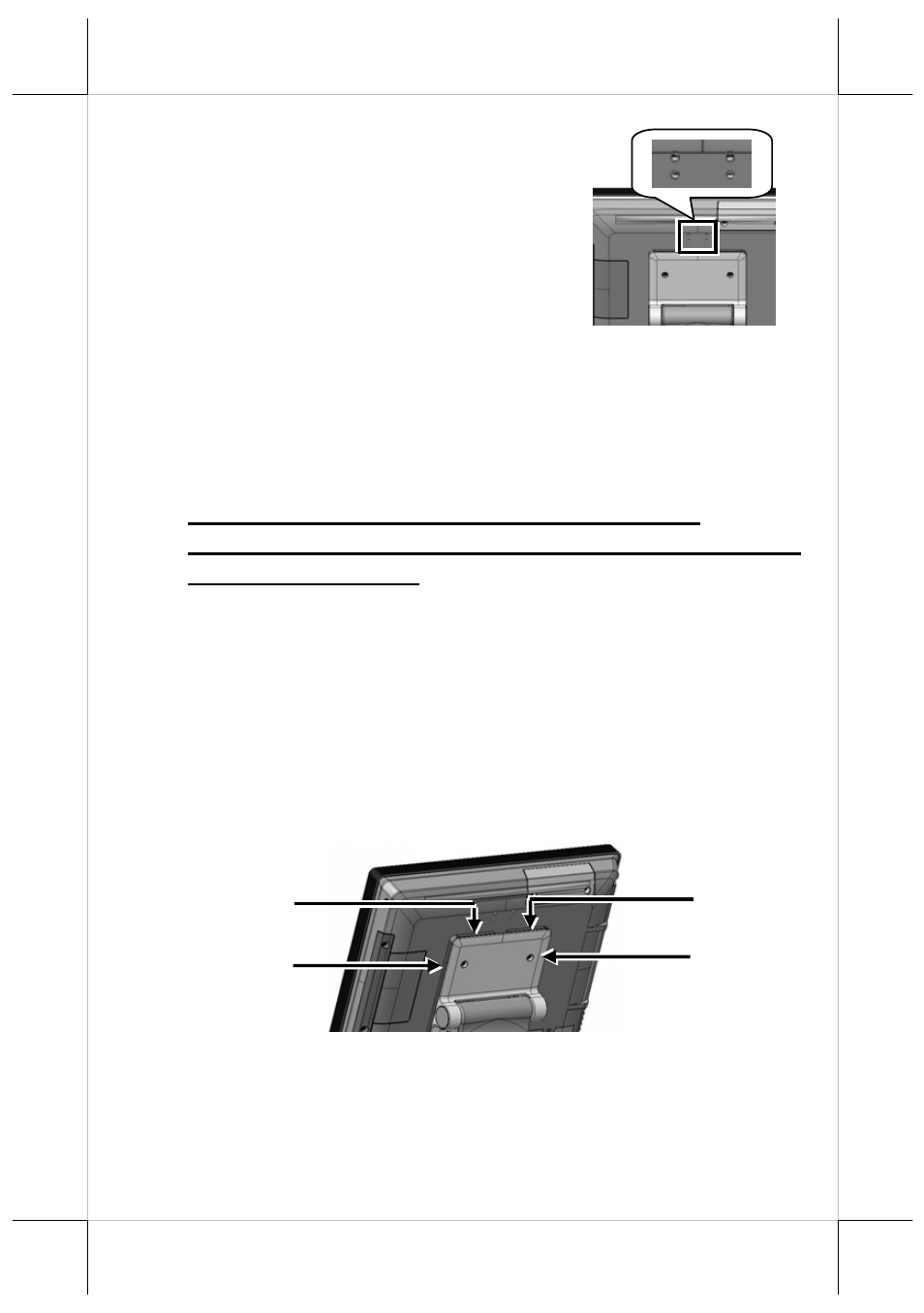
There are four cable stoppers, upper right stopper, lower right
stopper, upper left stopper, and lower left stopper, formed
between the rear side of terminal and the viewing-angle
adjustment plate of base stand. The cable stoppers are provided
to route and secure the cable of customer pole display or
second LCD monitor.
Lower left stopper
Upper left stopper
Upper right stopper
Lower right stopper
With across reference to the figures below, follow the steps to
route and secure the cable.
At step 1, choose the left side or right side to route and secure the
cable.
10