Posiflex IVA XT-3815 User Manual
Page 11
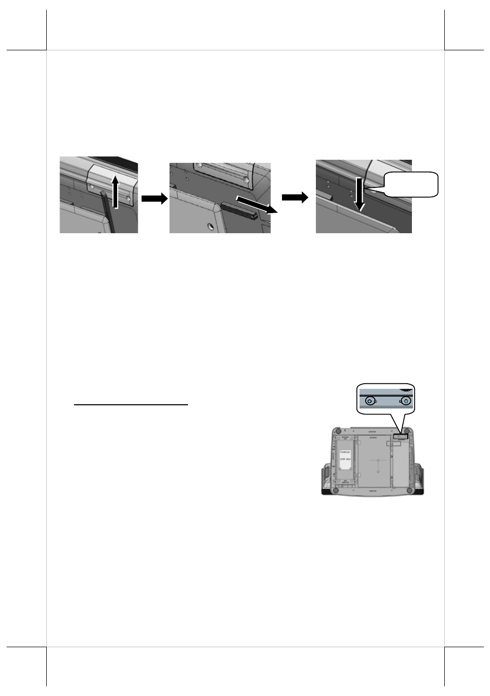
At step 2, if the right side is chosen, for example, push the lower
right stopper (long) upward with your thumb to remove, and then
push the upper right stopper (short) to the right with your thumb
to remove.
At step 3, draw the cable through the cavity between the rear side
of terminal and the viewing-angle adjustment plate of base stand.
3
Cable
1
2
At step 4, push the upper right stopper (short) to the left with your
thumb and then push the lower right (long) downwards with your
thumb to secure the cable.
For the detailed description of routing and securing the cable of
customer pole display or second LCD monitor, refer to the XT-
3615/3815 technical manual or the user manual of PD- or
LM/TM-series peripheral kit.
Onto the Base Stand
11
GEN 8E Base Stand
UPS Battery Kit
Before installing the UPS battery kit,
remove the 2 circled screws from the
UPS battery kit cover located at the
right compartment of the bottom side
of the base stand, as shown in the right
figure.
If you install both the hard disk drive kit and the UPS battery
kit, firstly install the hard disk drive kit and then the UPS
battery kit. For the detailed description of installation of the
UPS battery kit, refer to the XT-3615/3815 technical manual
or the user manual of UPS battery kit.