Posiflex IVA XT-3815 User Manual
Page 15
Advertising
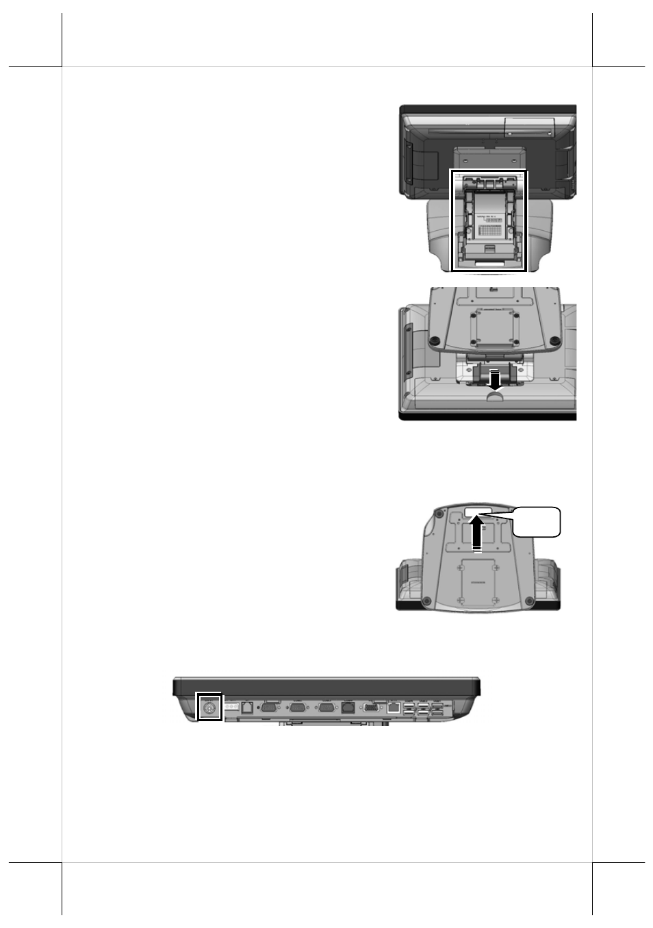
5. The cable cover and the neck cover
are well removed, as shown in the
right figure.
6. Then, slide the cable arrangement
cover to remove from the base stand.
After removing the covers illustrated above, follow steps made
below to route the cables from the bottom of base stand to the I/O
interfaces of the main unit.
7.
Make the connectors, which will
be connected to the I/O interfaces
of main unit, pass through the
hole A of the bottom of base
stand.
8.
Connect the connectors of cables to the I/O interfaces of
main unit.
A
CAUTION: Before connecting the power cable to the power jack of
main unit, do NOT touch any metal pin of the connectors
or circuits to avoid high voltage hazard or electrostatic
discharge damage.
15
Advertising