M~ m, Electrical connection diagram – REMKO ETF 400 User Manual
Page 15
Advertising
+
+
M
~
M
~
L1 N
PE
h
aC
Kompressor
S2
H1
H2
S3
M1
M2
Y1
P1
S1
K1
230V 50Hz
2
3
1
H
C
R
S
C
7
6
5
2
8
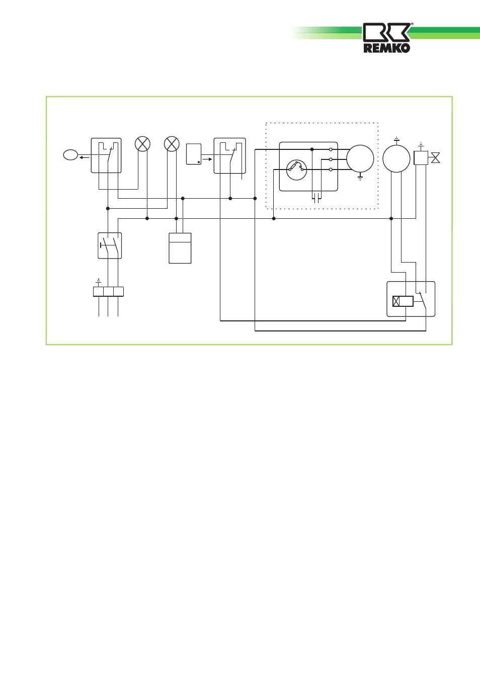
Electrical connection diagram
H1
=
Control lamp (yellow = container full)
H2
=
Control lamp (green = in operation)
K1
=
Time relay (t = 30 min.)
M1
=
Compressor motor
M2
=
Fan motor
P1
=
Operating hours counter
S1
=
Operating switch
S2
=
Microswitch (float)
S3
=
Defrost - thermostat
Y1
=
Defrost - solenoid valve
We reserve the right to modify the dimensions and constructional design as part of the ongoing technical development process.
15
Advertising
This manual is related to the following products: