Setup guide – SoundTraxx SurroundTraxx User Manual
Page 19
SurroundTraxx User’s Guide
Setup Guide Page 1:14
SurroundTraxx User’s Guide
Setup Guide Page 1:15
For the purpose of the SurroundTraxx setup, a detailed electrical schematic
is not required, but a basic schematic is an important step in separating the
layout into blocks, which is a prerequisite to defining your sound zones. The
example schematic refers to the same layout as the Rio Grande Southern
track plan presented on the previous pages. Notice that this is a much
simplified view, disregarding the curves and loops indicated on the track plan.
The schematic helps you assess the factors that affect the block divisions.
For example, you wouldn’t want to place a block boundary in the middle of
a siding. Instead, the boundary should occur at one end of the siding or the
other. Likewise, a wye or yard should usually be confined to a single block.
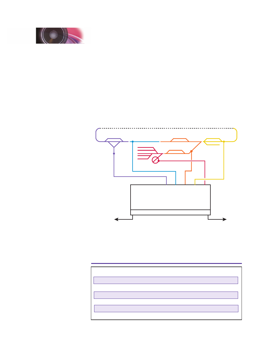
Even if you’re not using block detection with signaling devices, it’s helpful to
plan your blocks as if signaling were part of the picture. This example shows
the same schematic separated into blocks and wired to the block detectors.
Lizard Head
Summit
Ophir Loop
Telluride
Palisade
Silver Falls
Vance Jct.
Block
0
Block
2
Block
4
Block
6
Block
8
Block 10
Block 12
Block 14
To SurroundTraxx
To Command
Station
BDL 168
Transponding Blocks
If you find later on that your defined block boundaries aren’t perfect, it’s
usually fairly simple to adjust them. As shown above, we separated the
schematic into blocks, the colors corresponding to the speaker wire output
color and sound zone based on the SurroundTraxx default values for each
sound zone and transponding blocks which are shown on the table below.
Sound Zone
Speaker Wire Color
Transponding Block(s)
1
Red
0
2
Yellow
2
3
Orange
4
4
Blue
6
5
Purple
8
6
Green
10
SurroundTraxx Sound Zones (default setting)
Setup Guide