Super Systems 9120 RPSC User Manual
Page 14
Model 9120 Redundant Probe System - Color
4580 – Redundant Probe System – Color
Page 14 of 23
calibration
. There are two analog outputs each with a zero and span value.
Equipment needed
A certified calibrator(s) with the ability to source and measure millivolts, milliamps and thermocouples is
required. The appropriate connection leads are also required. A 24VDC 75-watt power supply is required.
The operator interface method requires a PC with the Configurator software loaded. An Ethernet crossover
cable is required. It is important to note that when performing a zero or span calibration,
do not use
regular thermocouple wiring. Instead, use any kind of regular sensor wire, or even regular copper wire.
To perform the calibrations, the user will need a calibrator that is capable of sourcing volts, millivolts, and
temperature.
Calibration Procedure
The calibration procedure for an input or output will be the same regardless of which operation is being
performed.
1. Zero Input: Source a zero mV value to the terminals. Press the Calibrate button.
2. Span Input: Source a specific mV value to the terminals and enter the value in the box. Press the
Calibrate button.
3. Zero Output: Press the Ready button, which will set the output to 0%, or 4 mA. Measure the
current at the terminals and input the measured value. In the number box, use the arrows or tap
the box to enter the value with the key pad. Press the Calibrate button.
4. Span Output: Press the Ready button, which will set the output to 100%, or 20 mA. Measure the
current at the terminals and input the measured value. In the box, use the arrows or tap the box
to enter the value with the key pad. Press the Calibrate button.
5. Cold Junction Trim: Enter the temperature of the input.
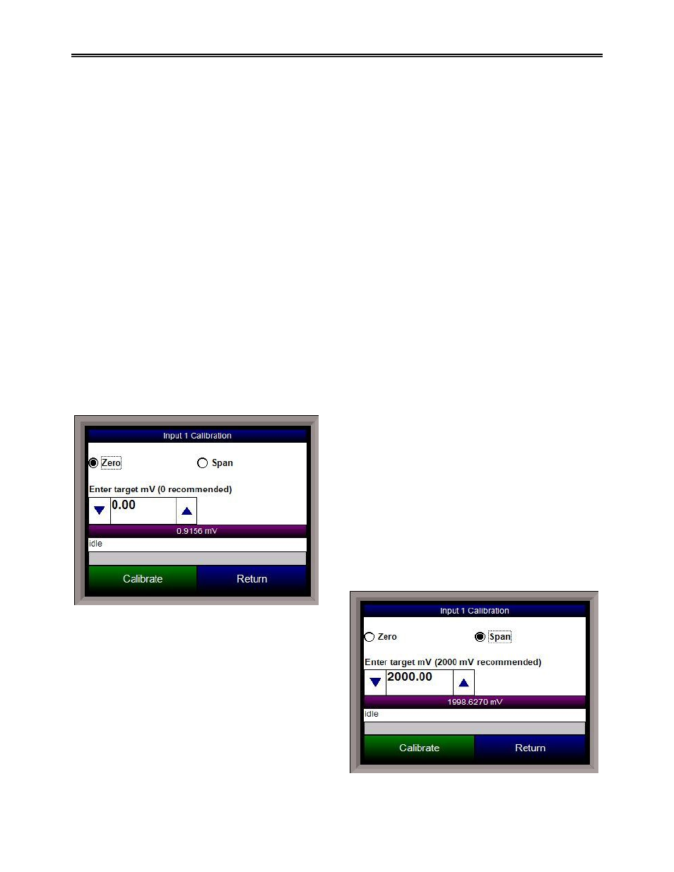
Input - Zero Calibration
To perform a zero calibration on an input, verify that
the “Zero” option at the top is selected. Select the
target millivolts that will be sourced.
Note – For a
zero calibration, it is recommended that 0 mV be
sourced
. The recommended millivolt source value will
be displayed as well. The mV value will be displayed
on the screen. Press the Calibrate button to begin
the calibration. The calibration status will be displayed
on screen. When it is over, the screen will display
“idle” once again. Once the zero calibration has
finished, the span calibration can be performed.
Input – Span Calibration
To perform a span calibration on an input, verify that
the “Span” option at the top is selected. Select the
target millivolts that will be sourced.
Note – For a
span calibration, it is recommended that 90 %
of the full range be sourced
. The recommended
millivolt source value will be displayed as well. The
mV value will be displayed on the screen. Press the
Calibrate button to begin the calibration. The
calibration status will be displayed on screen. When it
is over, the screen will display “idle” once again.