Super Systems 9120 RPSC User Manual
Page 9
Model 9120 Redundant Probe System - Color
4580 – Redundant Probe System – Color
Page 9 of 23
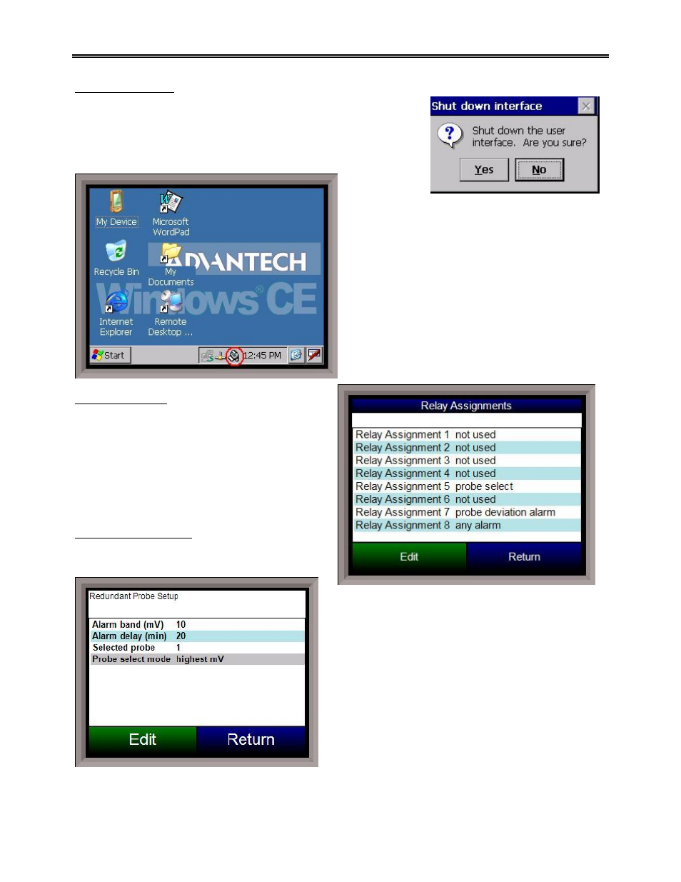
Shut down interface
This option will shut down the RPS unit interface. This option can be
used before turning off the power to the RPS unit to verify that all the
information has been saved. The user will need to verify the
shutdown process. Once the interface has been shut down, it can be
restored simply by cycling power to the unit, or by pressing the
reboot button on the screen.
Relay Assignments
This screen will display a description of the eight
relay assignments. The eight “Outputs” on the
front of the unit represent the eight relay
assignments, where Output #1 = Relay
Assignment 1, etc. Most of the relays in the RPS
are not used. All of the relay assignments are
fixed in the RPS. Relay 5 is the probe select relay.
Relay 7 is the probe deviation alarm.
Redundant Probe Setup
This menu option will allow the user to configure
the RPS setup.
Alarm band (mV)
This is the millivolt difference that must be observed for
the RPS to change probes. For example, when the RPS
is selecting the highest probe with probe 1 as 1055 mV
and a band of 20 mV, and if probe 2 hits 1076 mV, the
RPS will start counting down the Alarm Delay timer
(below). When the delay times out, probe 2 would be
selected. If probe 2 comes back in band (drops to
1075), the timers starts over again. The range is 0 to
600.
Alarm delay (min)
The number of minutes that the RPS waits to activate