Parts of the fw-1804, Front panel – Teac FW-1804 User Manual
Page 7
TASCAM FW-1804
7
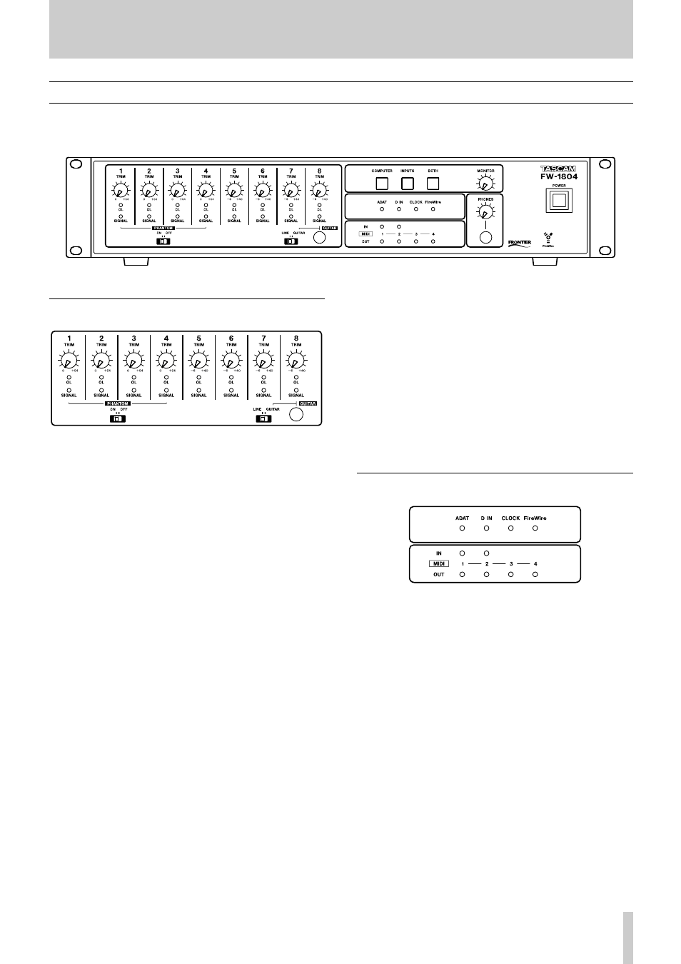
Parts of the FW-1804
Front Panel
The FW-1804 front panel is conveniently grouped into logical areas.
Input Section
TRIM controls
Analog level controls for the input level of the mic (XLR)
inputs 1 through 4, and line inputs 1 through 8. Their func-
tion is the same regardless of the monitor mode selected.
Note that the best signal-to-noise ratios are achieved by
maximizing the level of analog inputs at the A/D convert-
ers. For the mic and line inputs of the FW-1804, the TRIM
controls provide the means for optimizing these levels.
OL indicators
The OL indicators light to indicate a signal peaking at
–2.5dBFS or higher by default (this level is adjustable
between 0.0 dBFS and 5.0 dBFS, in 0.5 dB increments,
using the FW-1804's software Control Panel). When one of
these indicators lights, it indicates an overloaded input—
reduce the level of the input to the channel until the indica-
tor goes out.
SIGNAL indicators
The SIGNAL indicators light to indicate the presence of an
audio signal at the corresponding analog input. These indi-
cators light when the signal level is –42 dBFS or higher.
These indicators and the OL indicators indicate signal lev-
els to the eight analog inputs regardless of the monitor
mode selected.
PHANTOM switch
Use this switch to enable phantom power for the micro-
phone jacks.
CAUTION
Microphones should not be connected to or disconnected
from the FW-1804 with phantom power switched on.
Unbalanced dynamic microphones should never be con-
nected to phantom-powered connectors.
GUITAR/LINE switch
Affects LINE IN 8 only. When this is set to GUITAR, the
input impedance then matches that of an electric guitar or
passive bass. For all other instruments, leave this in the
LINE position.
Indicators
ADAT indicator
This indicator lights when a valid clock signal in ADAT
format is received.
D IN indicator
This indicator lights when a valid clock signal in S/PDIF or
TOSLINK format is received.
CLOCK indicator
This indicator lights when the internal clock is locked to the
selected sampling frequency.
FireWire indicator
This indicator lights when a valid IEEE 1394 (FireWire)
connection is made between the FW-1804 and the host
computer.
MIDI IN and OUT indicators
These light momentarily when MIDI activity is detected on
the appropriate port(s). These indicators function independ-
ently of the monitor mode.