Section 2.5.2 – Verilink 1558A (34-00228) Product Manual User Manual
Page 11
1558A APS
2-4
Installation
• Alarm on Loss of Signal
• AMI/B8ZS Line Coding for DTE and NET
• CSU Functions Enabled/Disabled
• Path Revert, Enabled/Disabled
• DTE Framing ESF/D4 (NET framing is fixed as ESF)
The following table describes the DIP switch settings con-
trolled by Switch S2.
Option Switch S3
This is an 8 -position DIP switch. It is used to set the 1558A
unit address ID for the NET A hardware and the NET B
hardware. Unique addresses must be optioned for each
1558A unit when multiple units are co-located and a 1559
Site Manager is being used. If no manager is being used, the
user should leave the DIP switches in the factory default
positions (all in the OFF or DOWN position). This config-
ures the unit for NET A address 1 and NET B address 2.
The following table indicates how to configure the address
settings for the first six 1558A units.
NOTE: When connecting to the SUPV port using the APS
local access software, the 1558A NET A/B addresses are
viewed as a single unit address and are displayed as 1.01
for addresses 1 and 2, 1.02 for addresses 3 and 4, etc.
Option Switch S4
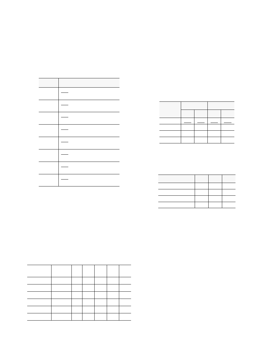
This is an 8 -position DIP switch. The following tables indi-
cate how to set the DIP switches for the various LBO and
DSX level settings. Note that S4-8 is not used (spare).
Positions 1 - 4 are used to set the LBO transmit level for the
NET A and NET B T1 signals. The factory default is 0 db
for the LBO settings.
Positions 5 - 7 are used to set the DSX signal level (in feet)
for the DTE port. The factory default is 0 to 133 feet for the
DTE DSX setting.
2.5.2
ROM Configuration
The 1558A may be configured to boot operational parame-
ters from the internal ROM (read only memory). To config-
ure the 1558A to boot from ROM, set S1-7 and S1-8 to the
ON position and S1-6 to the OFF position. With these set-
tings, the 1558A will always boot (at power up) the unit
configuration parameters from the internal ROM settings.
The ROM unit parameters are listed below:
• Block ESF data link, both directions
• Regenerate CRC6, both directions
• Slave Operation
• B8ZS line coding, both directions
• ESF framing, both directions
• Revert mode, disabled
• Availability timer set to 60 seconds
• Errored seconds set to 20
• Consecutively errored seconds set to 2
Position
Switch S2 Description
1
OFF = Framing Errors, Enabled
ON = Framing Errors, Disabled
2
OFF = LOS, Enabled
ON= LOS, Disabled
3
OFF = NET/B, B8ZS
ON = NET/B, AMI
4
OFF = NET/A, B8ZS
ON = NET/A, AMI
5
OFF = DTE/B8ZS
ON = DTE/AMI
6
OFF = CSU Mode, Enabled
ON = CSU Mode, Disabled
7
OFF = Revert, Disabled
ON = Revert, Enabled
8
OFF = DTE, ESF
ON = DTE, D4
*APS Mgr.
Unit Pos.
NET A/B
Address
Pos
1
Pos
2
Pos
3
Pos
4
Pos
5 - 8
1.01
1/2
ON
OFF
OFF
OFF
OFF
1.02
3/4
ON
ON
OFF
OFF
OFF
1.03
5/6
ON
OFF
ON
OFF
OFF
1.04
7/8
ON
ON
ON
OFF
OFF
1.05
9/10
ON
OFF
OFF
ON
OFF
1.06
11/12
ON
ON
OFF
ON
OFF
LBO
NET A
NET B
S1
S2
S3
S4
0.0
DB OFF OFF OFF OFF
7.5
DB OFF ON OFF ON
15.0 DB
ON
OFF
ON
OFF
22.5 DB
ON
ON
ON
ON
DTE DSX Value
S5
S6
S7
1 to 133 ft.*
OFF
OFF
OFF
134 to 266 ft.
OFF
OFF
ON
267 to 533 ft.
OFF
ON
OFF
534 to 655 ft.
ON
OFF
OFF