Verilink 1558A (34-00228) Product Manual User Manual
Page 20
Operation
3-5
1558A APS
3.3.1
Supervisor Port
The front panel SUPV port allows the user to connect to the
1558A via a PC running the supplied APS LAPS (Local
Access protection software) application. This user interface
software allows the user to gain access to the unit configura-
tion data, unit status, unit performance, and perform local
and remote loopback testing.
Electrically, the SUPV port is RS232 and the data format is
19.2 Kb, asynchronous. The cable used to connect the PC to
the SUPV port is a DB9 (female) to 6-pin modular cable.
This cable is provided with the 1558A unit. The pin func-
tions for the SUPV port are shown in the following table.
3.3.2
Power Indicators
The 1558A has two green power LED indicators (Power A
and Power B). One or both of the indicators will be ON
when a nominal power source of -20 to -56 VDC is present
on the rear panel PWR A and PWR B screw terminals,
respectively. The indicator(s) will be OFF if the power is not
present at the respective power screw terminals. Only one
power input is required to operate the unit. If power redun-
dancy is crucial, both the Power A and Power B inputs
should be wired to an external -20 to -56 VDC source. The
1558A unit is shipped with a single 110 VAC to -48 VDC
wall power unit.
3.3.3
Bypass Indicator
The red BYPASS LED indicates whether or not the 1558A
is presently in a BYPASS mode of operation. The LED will
be ON if the unit has detected a CPU watchdog operational
fault. The LED will be OFF under normal operation.
When active, the BYPASS mode connects the NET A T1
facility directly to the DTE port. In this mode, all of the
active electronics are bypassed. That is, the only elements in
the path are passive line protection circuitry components for
the NET A port and the DTE port. During BYPASS opera-
tion, the 1558A acts only as a passive device and does not
perform any signal regeneration functions.
Activation of the BYPASS mode occurs when either the
CPU watchdog timer circuitry is defective (indicates a CPU
or software problem) or when power is removed from the
unit. The BYPASS mode is terminated when either the CPU
watchdog circuitry is determined to be normal or when
power is restored to the unit.
3.3.4
Locked Indicator
The user can manually force and lock either the A or B T1
path as the active path by moving the PATH SELECT switch
from the AUTO position to either the A or B Path Select
positions. This action will force the 1558A to use the
selected path. Also, the 1558A is now manually locked to
this path and will not switch from it, even if the selected
path is in a failed state or subsequently fails. When the
1558A has been manually forced to either the A or B PATH,
the amber LOCKED LED indicator will be on. Moving the
PATH SELECT switch back to the AUTO position will turn
off the LOCKED LED and restore normal APS operation.
Caution: Placing the 1558A in a manually locked
mode prevents the unit from performing automatic pro-
tection switching.
Pin
SUPV Port Wiring
1
Not Used
2
Ground
3
Data, Out
4
Data, In
5
Ground
6
Not Used
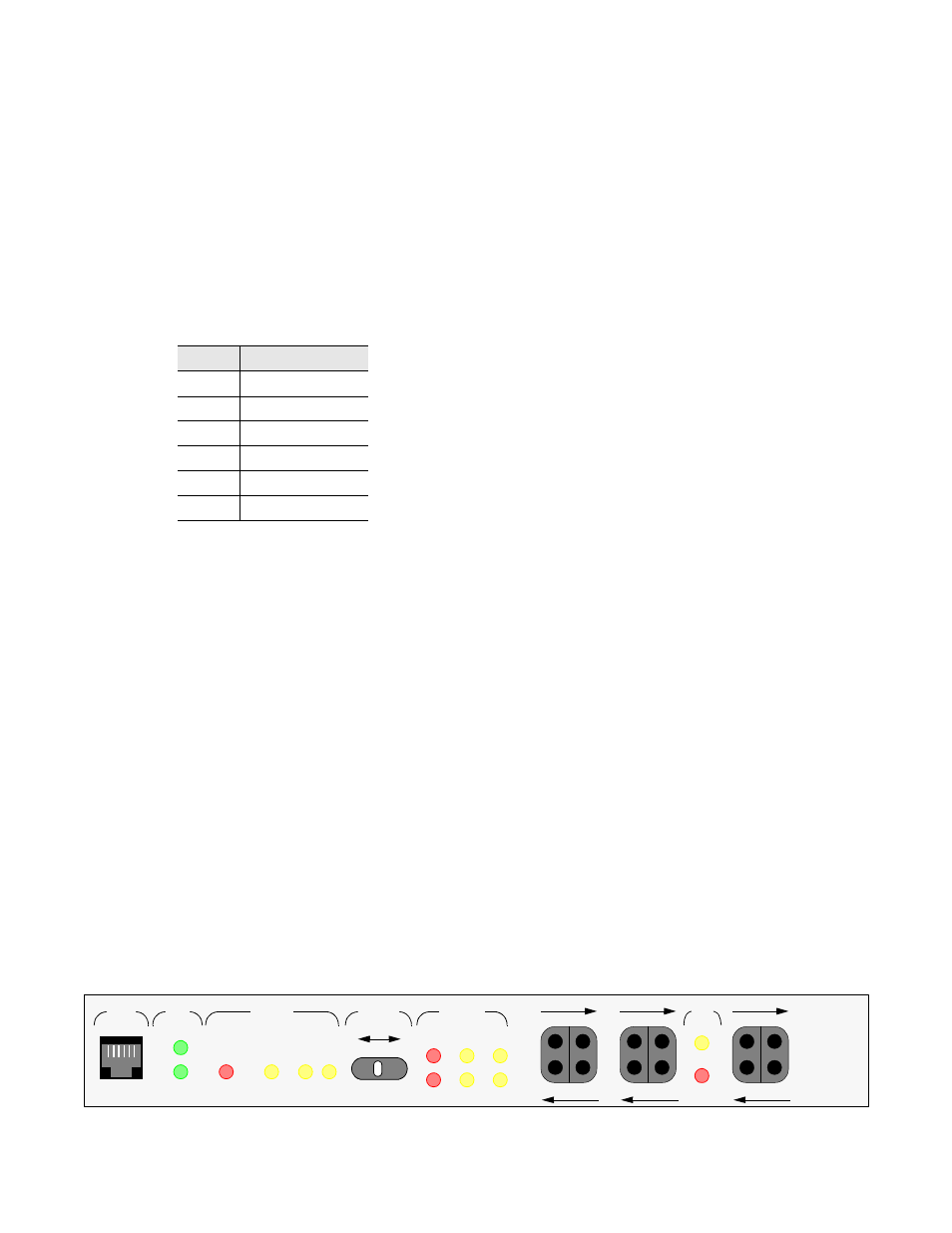
Figure 3-2
1558A Front View
A
SUPV
PWR
B
STATUS
A
BYPASS
LOCKED
B
A
B
ALM
LOS
LP
A
SELECT
AUTO
PATH
B
STATUS
PATH
RX BRDG
TX BRDG
N
E
T
A
RX BRDG
TX BRDG
N
E
T
B
DTE
LOS
RX BRDG
TX BRDG
D
T
E
TxPORT
LP
1558A