6 equipment connection, 7 network connection, 8 network management – Verilink 2048 (34-00179) Product Manual User Manual
Page 12
Installation
2-5
2048 PMU/NTU
2.6
Equipment Connection
The equipment physical interface for both the stand-alone
unit and the chassis mounted unit is a standard RJ48C 8-pin
modular jack. A DB15 backplane is also an option for the
equipment interface. The pinout assignments are as follows:
NOTE: For 75 ¾ DB15 operation, the following pins
must be connected together: pins 2 & 9; pins 4 & 11.
For 120 ¾, leave as specified.
2.7
Network Connection
The network physical interface for both the stand-alone unit
and the chassis mounted unit is a standard RJ48C 8-pin
modular jack. A DB15 backplane is also an option for the
network interface. The pinout assignments are shown in the
following table.
2.8
Network Management
The 2048 PMU provides several means for user interface.
Using the configuration switch settings described in Section
2.5, the PMU may be configured and operated without fur-
ther interface. However, this mode does not allow access to
many of the capabilities of the unit.
For full software control and access to information, the
PMU has 3 ports which provide management functions
(SUPV, USER, and PTT ports). These ports may be used
for a VT100 terminal interface or for an EM8000 network
manager interface.
An element may be accessed by using an RS232 connection
from the serial port of the computer running the EM8000
program to the element’s SUPV, USER, or PTT ports.
These ports are described in the following paragraphs.
2.8.1
Supervisory Port
The front panel ‘SUPV’ port serves several functions. A
modem may be connected to this port for remote access or
use of the COA (call on alarm) feature. A computer con-
nected to the SUPV port can access the embedded ‘terminal
interface’ firmware for PMU software control (refer to the
‘Terminal Operations’ chapter).
For cabling convenience, the EM8000 element manager
may be directly connected to the ‘SUPV’ port. When a
group of elements is connected in an NMS chain, the
EM8000 may be connected to the supervisory port of any
one of the elements. This element can then route messages
onto the NMS chain to reach the other elements. Refer to
Section 2.8.2 for more information on the EM8000.
The SUPV port is an independent serial interface into the
unit and connecting to it does not interrupt NMS port traffic.
Pin
RJ48 Interface
Pin
DB15 Interface
1
Data Out
1
Data In
2
Data Out
2
Frame Ground
3/6
Not Used
3
Data Out
4
Data
In 4
Frame
Ground
5
Data
In 9
Data
In
7/8
Chassis Ground
11
Data Out
Pin
RJ48 Interface
Pin
DB15 Interface
1
Data
In 1
Data
Out
2
Data
In 2
Not
Used
3/6
Not
Used 3
Data
In
4
Data Out
4
Not Used
5
Data Out
9
Data Out
7/8
Chassis Ground
11
Data In
8
15
1
9
1
9
8
15
IN
OU
T
USER
1
2
3
4
5
6
IN
OU
T
PTT
EQPT
NET
Power/Alarm
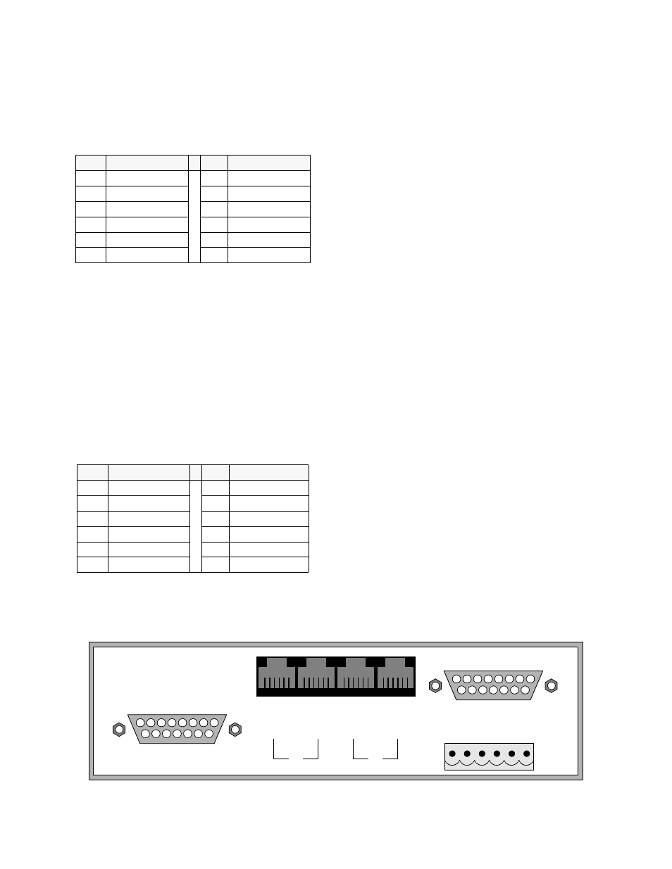
Figure 2-2
2048 Rear Panel with DB15 Connector
6
1
6
1