Data normal or inverted -3 program flash -3, Address switch s2 -3 configuration switch s3 -3, Nms port rate -3 supv port rate -3 – Verilink PRISM 3021 (34-00262) Product Manual User Manual
Page 11: Address switch s2, Configuration switch s3
Installation 2-3
PRISM 3021
D
ATA
N
ORMAL
OR
I
NVERTED
Position S1-7 is used to select if data is normal or inverted
as shown in Table 2-F.
Units at both ends of the circuit must have this
option set the same.
P
ROGRAM
F
LASH
Position S1-8 is used to enable or disable programming the
Flash memory as shown in Table 2-G.
When switch S1-8 is in the Up position,
the unit goes into download mode. After
downloading the unit, move S1-8 to the Down
position. If this switch is left in the Up position
and power is lost, the unit powers back up in the
download mode.
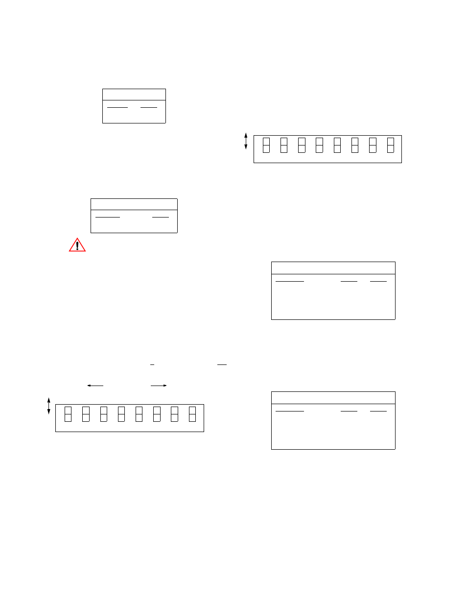
Address Switch S2
Switch S2 sets the unit address. When using the 3021 with
an 8100A Site Controller, each element must have a unique
unit address. The 8100A Site Controller can address up to 50
units (with addresses from 1 to 50). If the unit is not con-
nected to a site controller, the NMS unit address should be
left at the factory default setting of 1 where Position 1 is Up
and all other positions are Down (see Figure 2-3).
Figure 2-3 Switch S2
Switch S2 has eight positions used to create an 8-bit binary
code for an address in the range of 1 to 50. Switch position
S2-1 is the least significant bit (LSB) and S2-8 is the most
significant bit (MSB). If a switch is down, its value is 0. If
up, its value is that of the upper location. The values are
additive. For example, to set a unit address to 5, position S2-
3 (binary value is 4) and position S2-1 (binary value is 1)
would be set Up for a unit address of 5 (4 + 1). All other
positions would be set Down. If all the switches are Down,
the address is 1.
Configuration Switch S3
Switch S3 (Figure 2-4) is used to set the configuration
parameters listed in the following paragraphs.
NMS P
ORT
R
ATE
Positions S3-1 and S3-2 select the NMS port rate as shown
in Table 2-H. This is a serial RS-232 DCE port configured
for eight bits, no parity, and one stop bit. If the 3021 is being
used with the 8100A, the NMS rate of all units must be set
the same.
SUPV P
ORT
R
ATE
Positions S3-3 and S3-4 select the SUPV port rate as shown
in Table 2-I. This port is used to access the embedded termi-
nal interface. This is a serial RS-232 DCE port configured
for eight bits, no parity, and one stop bit.
Table 2-F Data Normal or Inverted
Data
S1-7
Normal
Down
Inverted
Up
Table 2-G Program Flash
Program Flash
S1-8
Disabled
Down
Enabled
Up
LSB
MSB
Binary values
1
2
4
8
16
32
64
128
0
0
0
0
0
0
0
0
7
6
5
4
3
2
1
Do
wn
Up
8
Table 2 -H NMS Port Rate
NMS Port Rate
S3-1
S3-2
19200 bps
Down
Down
9600 bps
Down
Up
2400 bps
Up
Down
1200 bps
Up
Up
Table 2-I SUPV Port Rate
SUPV Port Rate
S3-3
S3-4
38400 bps
Down
Down
19200 bps
Down
Up
9600 bps
Up
Down
2400 bps
Up
Up
7
6
5
4
3
2
1
D
o
w
n
U
p
8
N
M
S
P
o
rt
N
M
S
P
o
rt
S
U
P
V
P
o
rt
D
T
E
R
a
te
C
h
an
n
el
R
at
e
A
ss
ig
n
m
en
t
M
u
lt
ip
li
er
B
o
o
t
M
o
d
e
R
at
e
S
U
P
V
P
o
rt
R
at
e
B
o
o
t
M
o
d
e
Figure 2-4 Switch S3
R
at
e