Configuration switch s4 -5 dte rate -5, Jumpers -5, Jumpers – Verilink PRISM 3021 (34-00262) Product Manual User Manual
Page 13
Installation 2-5
PRISM 3021
C
ONFIGURATION
S
WITCH
S4
DTE R
ATE
Positions S4-1 through S4-5 select the DTE rate as shown in
Table 2-N. The DTE rate multipliers (N
×
56 and N
×
64) are deter-
mined by setting switch S3-7 (see Table 2-K on page 2-4).
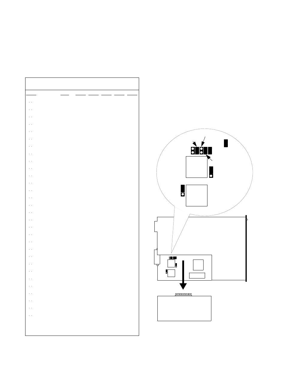
Jumpers
To configure E1 network impedance, remove the E1-DTE
card as shown in Figure 2-6 and place the jumpers as
explained in the following paragraphs.
E1 N
ETWORK
I
MPEDANCE
The network termination of the 3021 can be selected for
either 75 or 120 ohms. Placing the jumpers for J5 and J12 in
the center post and the post labeled 120 configures the unit
for 120-ohm termination. Placing the jumpers for J5 and J12
in the center post and the post labeled 75 configures the unit
for 75-ohm termination.
S
TATION
C
LOCK
S
IGNAL
L
EVELS
The 3021 accepts an RS-423-compatible station clock input.
Contacts are provided on the rear of the 1051 chassis (12-
slot chassis) to permit connection to an external timing
Table 2-N DTE Rate
DTE
Rate
N
×
56
(kbps)
N
×
64
(kbps)
S4-1
S4-2
S4-3
S4-4
S4-5
N=31
1,
2
1736
1984
Down Down Down Down Down
N=30
1
1680
1920
Up
Down Down Down Down
N=29
1
1624
1856
Down Up
Down Down Down
N=28
1
1568
1792
Up
Up
Down Down Down
N=27
1
1512
1728
Down Down Up
Down Down
N=26
1
1456
1664
Up
Down Up
Down Down
N=25
1
1400
1600
Down Up
Up
Down Down
N=24
1
1344
1536
Up
Up
Up
Down Down
N=23
1
1288
1472
Down Down Down Up
Down
N=22
1
1232
1408
Up
Down Down Up
Down
N=21
1
1176
1344
Down Up
Down Up
Down
N=20
1
1120
1280
Up
Up
Down Up
Down
N=19
1
1064
1216
Down Down Up
Up
Down
N=18
1
1008
1152
Up
Down Up
Up
Down
N=17
1
952
1088
Down Up
Up
Up
Down
N=16
1
896
1024
Up
Up
Up
Up
Down
N=15
840
960
Down Down Down Down Up
N=14
784
896
Up
Down Down Down Up
N=13
728
832
Down Up
Down Down Up
N=12
672
768
Up
Up
Down Down Up
N=11
616
704
Down Down Up
Down Up
N=10
560
640
Up
Down Up
Down Up
N=9
504
576
Down Up
Up
Down Up
N=8
448
512
Up
Up
Up
Down Up
N=7
392
448
Down Down Down Up
Up
N=6
336
384
Up
Down Down Up
Up
N=5
280
320
Down Up
Down Up
Up
N=4
224
256
Up
Up
Down Up
Up
N=3
168
192
Down Down Up
Up
Up
N=2
112
128
Up
Down Up
Up
Up
N=1
56
64
Down Up
Up
Up
Up
1
This selection is not valid if the Channel Assignment is set to
Alternating.
2
This selection is not valid for CAS mode.
T1
T2
J14
J15
J16
J17
J5
J12
J13
F
ro
n
t
E1-DTE
Option Card
U6
U5
T1
T2
3021
Figure 2-6 Jumper Placement on the 3021
75
120
75
120
J6