General, Introduction -1, Introduction – Verilink PRISM 3021 (34-00262) Product Manual User Manual
Page 5
General 1-1
PRISM 3021
1. General
Introduction
The TxPORT PRISM 3021 is a modular, single port, frac-
tional E1 NTU/DSU. The PRISM 3021 provides all the
standard, high-quality features found in all PRISM products.
TxPORT has a complete E1 solution with the combination
of the 3021 E1 NTU/DSU, 2048 PMU/NTU, and 8100A
Site Controller.
The PRISM 3021 can be installed in minutes. Card-edge
switches allow for all major configuration items to be
quickly selected. Full configuration and maintenance selec-
tions are available through the built-in VT100 user interface.
Configuration can also be done using Telnet or SNMP Sets
and Gets if the 8100A Site Controller is the manager.
The PRISM 3021 can be ordered with ITU V.35 or EIA-530
interfaces as well as a E1-DTE option card. Channel assign-
ments can be customized to a variety of configurations.
Trouble isolation is simple with the PRISM 3021. Loops can be
generated for the near-end unit as well as for the far-end unit.
Multiple loops allow segmentation of the network and isolating
the problem quickly. Loops include line loopbacks, payload
loopbacks, digital loopbacks, and channelized loopbacks.
A full complement of Bit Error Rate Testing (BERT) pat-
terns is available on the PRISM 3021. The different stress
patterns provide a greater diagnostic capability. BERT pat-
terns are initiated from either the front panel switch or
through the user interface. Testing can also be initiated from
the 8100A Site Controller.
The PRISM 3021 provides several ways to manage a net-
work. An end-to-end data link provides remote communica-
tions to the distant end. Configuration and maintenance of
the remote unit can be done from the central site. The
8100A Site Controller provides a single interface point to
manage up to 50 units. The 8100A even provides an SNMP/
Telnet access for the PRISM 3021 and complete network
management from one central LAN management station.
The chapters in this manual are arranged as follows:
Introduction - Describes product specifications, FCC and
warranty information, in addition to TxPORT ordering num-
bers and Customer Service telephone numbers.
Installation - describes unit mounting, switch configuration,
interface connections, and unit powering.
Operation - describes the front panel controls and indica-
tors, unit testing, and control port features.
LOC
FAR
D
T
E
TD
RD
RTS
DTR
STATUS
T
R
A
N
S
P
O
R
T
®
E1 CSU/DSU
N
E
T
BV/CR/FE
LOS/OOF
AIS
REM ALM
LOOP
TST
ERR
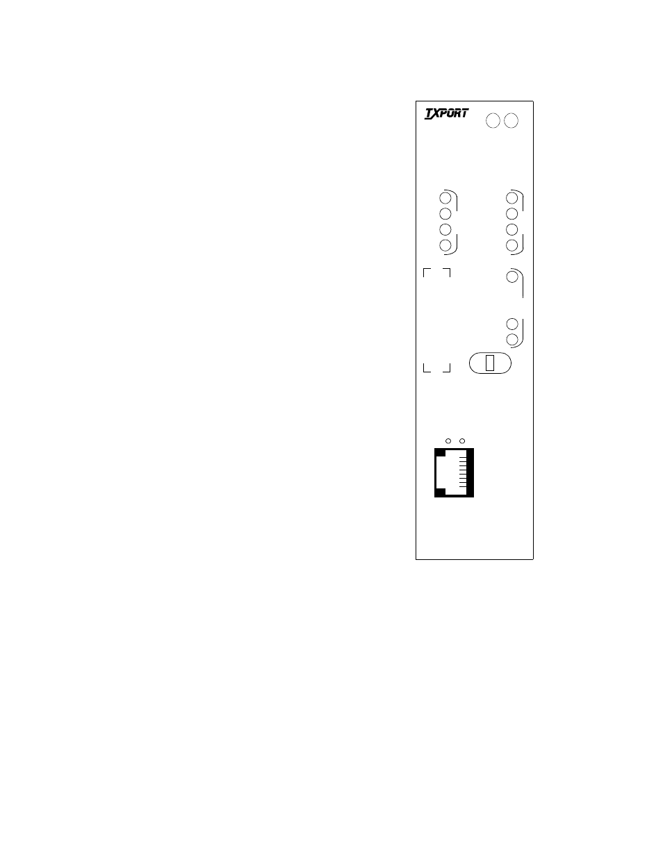
Figure 1-1 3021 Front Panel
S
U
P
V
1
8
3021
T
S
T