Front panel testing -2, Test switch -2 supervisory port -2, Upgrading software -2 – Verilink PRISM 3021 (34-00262) Product Manual User Manual
Page 22: Front panel testing, Upgrading software, Network indicators, Testing indicators, Test switch, Supervisory port
3-2 Operation
PRISM 3021
Network Indicators
9.
BV/CR/FE: This LED lights when the unit detects
bipolar violations, cyclic redundancy checking errors,
or framing errors.
10. LOS/OOF: This LED flashes when the unit detects a
loss-of-signal condition or lights continuously during an
out-of-frame condition from the DDS network.
11. AIS: This LED lights continuously when the network
interface is receiving an Alarm Indication Signal.
12. REM ALM: This LED lights when the network inter-
face is receiving a Remote Alarm Indication.
Testing Indicators
13. LOOP: This LED lights continuously when the net-
work interface is in a line loopback.
14. TST: This LED indicates that a BERT is in progress.
15. ERR: This LED lights when BERT-pattern errors are
detected.
Front Panel Testing
The previous section gave a brief description of each front
panel control. This section explains the front panel test
functions. Testing may also be performed using software
control from the 8100A Site Controller or the Terminal
Interface program (refer to chapter Terminal Operation).
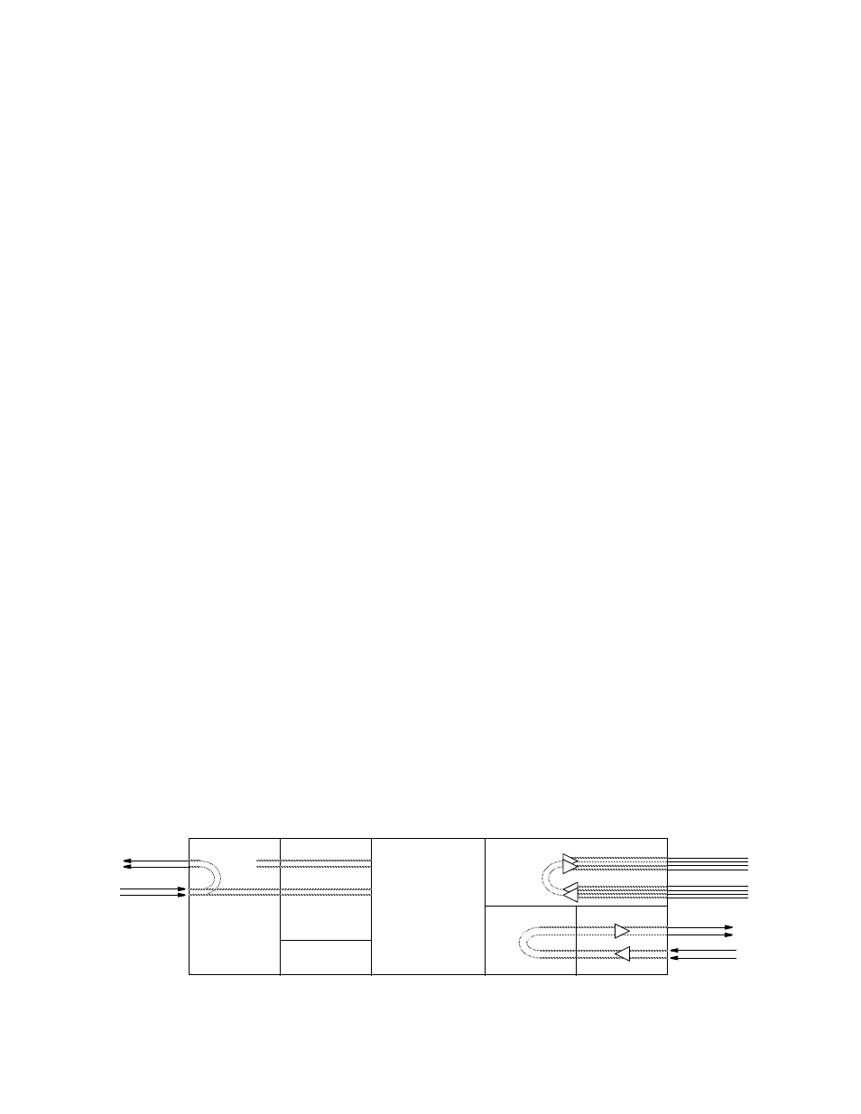
Test Switch
This three-position switch (labeled FAR/LOC) is used for
local testing. Figure 3-2 shows the type of loop for far and
local testing.
When in the FAR position, the 3021 sends five seconds of
IBLC (in-band loop code) and then sends the BERT pattern
last selected in the user interface (see Patterns on page 4-9).
The default is QRSS. When transmitting a test pattern, the
TST LED remains On. The ERR LED lights for one second
when a bit error or sync loss on the returned data is
detected.
When the test switch is returned to the center position, the
3021 sends five seconds of loopdown code and then returns
to its normal operating mode.
When the Test switch is in the LOC position, the 3021 per-
forms a network LLB as shown in Figure 3-2, and the
LOOP LEDs light.
Supervisory Port
This 8-pin modular RS-232 jack provides direct terminal
access for controlling the 3021 and gathering status and per-
formance data.
The supervisory port serves several functions. A terminal
may be connected to this port for external software control.
A modem may be connected for remote access. The port
supports the call on alarm feature. A ComView NMS
device, such as a 8100A Site Controller, may be connected
to this port. Refer to Power Connection on page 2-9 for
connection information.
Upgrading Software
The FAR/LOC switch is also used to set the SUPV port rate
when upgrading software for the 3021 (see PC Setup on
page A-1).
DSX1, 1' -to 655'
to cross-connect
Figure 3-2 Network LLB
Network Interface
Framer /Deframer
Multiplexer
Receivers /Drivers
Receivers/Drivers
BERT Generator /
Detector
EIA-530 or V.35
(100' max.)
Framer /Deframer
DTE (DSX1)
RJ-48C
From
NET
To
NET
To
NET
From
NET
5
4
2
1
To Network
From Network
RJ-48C
5
4
2
1
To
Ports
From
Ports
NET
LLB