External clock connection -10 – Verilink PRISM 3021 (34-00262) Product Manual User Manual
Page 18
2-10 Installation
PRISM 3021
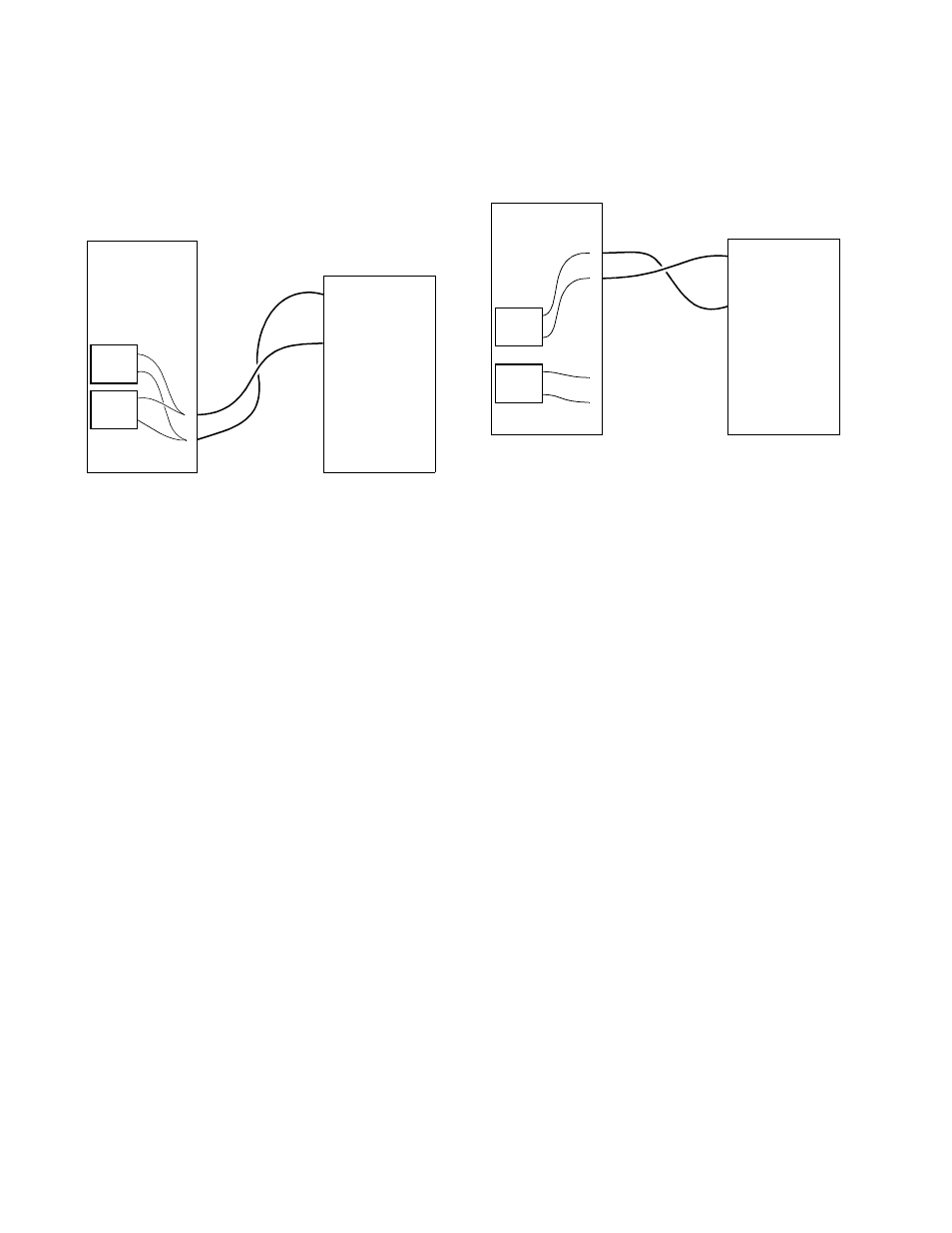
Redundant Power Source: The power board allows the
connection of two independent -48 VDC supplies operated
in a redundant mode. All slots are powered from the com-
bined input from the A and B power supplies (the A and B
buses are in a logical OR arrangement). If one supply fails,
the other powers the entire chassis. An example using a
TxPORT 1041 power supply is shown in Figure 2-11.
Single Power Source: Using a single power source is
essentially the same as the redundant configuration with
power supply B not operational. If the redundant power
board is not used, the A and B buses must be connected
together as shown in Figure 2-12.
External Clock Connection
Contacts on the rear of the 1051 chassis permit connection
to an external timing source (using TB1, pins 1 and 2). The
station timing is configured through the Terminal Interface
(see Line Parameters on page 4-13) or through the configu-
ration switches (see Timing Source on page 2-2).
TxPORT
1051
Chassis
TxPORT
1041
Power
Supply
–
+
GND
1
2
3
4
5
6
TB2
Figure 2-11 Wiring for Redundant Power Sources
PS A
PS B
TxPORT
1051
Chassis
TxPORT
1040
Power
Supply
–
+
GND
1
2
3
4
5
6
TB2
Figure 2-12 Wiring for a Single Power Source
PS A
PS B
–
+
GND