Operation, Introduction, Front panel controls and indicators – Verilink PRISM 3021 (34-00262) Product Manual User Manual
Page 21: General status indicators, Dte indicators, Test controls and indicators/terminal access
Operation 3-1
PRISM 3021
3. Operation
Introduction
This chapter describes general operation of the TxPORT
PRISM 3021 front panel. The 3021 may be controlled man-
ually using the front panel and the circuit board configura-
tion switches (configuration switches are discussed in Unit
Configuration on page 2 -1).
Chapter 4, Terminal Operation covers the firmware-con-
trolled Terminal Interface program, which gives the user
maximum control. The 3021 may also be controlled using
the 8100A Site Controller.
Factory default settings are underlined through-
out this manual.
Front Panel Controls and
Indicators
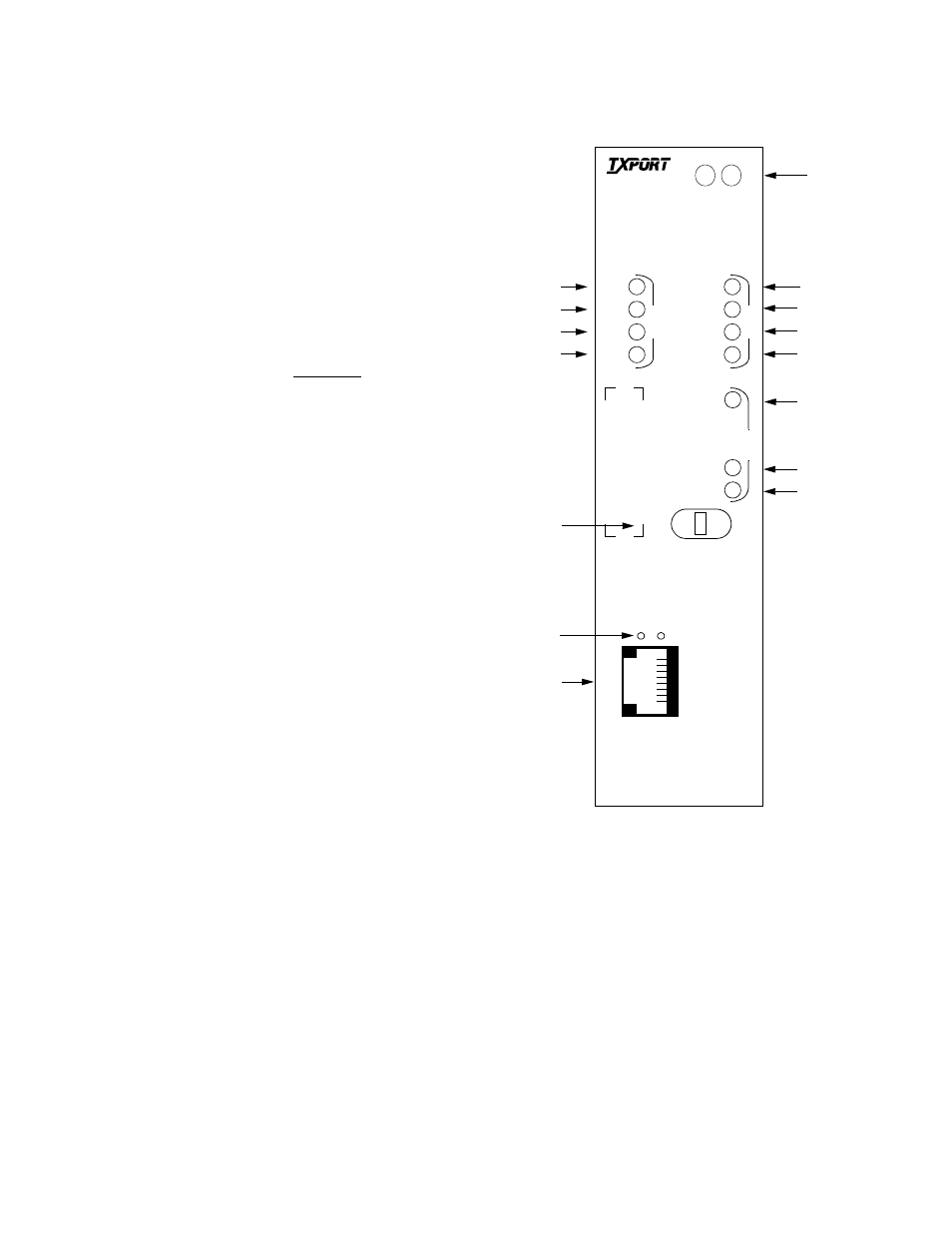
The front panel contains 15 LED indicators which convey sta-
tus, alarm, and test information. The front panel also contains
a test switch and a supervisory port connector. The following
descriptions refer to Figure 3-1.
General Status Indicators
1.
STATUS: The 3021 has two LED indicators on the
front panel bezel. These general status LEDs provide a
quick check of the 3021 operating condition (Alarmed
or Not Alarmed).
If neither LED is lit, the 3021 is not powered. If the
green LED is lit, the 3021 is powered and may be func-
tioning normally. If the red LED is lit, there is a fault
that exceeds alarm thresholds or another type of 3021
failure. The problem can usually be isolated by further
examination of the other front panel LEDs as described
below. Some errors can only be determined through the
terminal interface (for example, OOF).
DTE Indicators
2.
TD: This green LED lights during a mark condition on
the high-speed transmit data line.
3.
RD: This green LED lights during a mark condition on
the high-speed receive data line.
4.
RTS: This green LED lights when the request to send
signal is active.
5.
DTR: This green LED lights when the data terminal
ready signal is active.
Test Controls and Indicators/Terminal Access
6.
Test Switch: This switch (FAR/LOC) is used for local
testing and setting the SUPV port rate when download-
ing firmware for the Flash PROM. Refer to
Front Panel Testing on page 3-2 for more information.
7.
Activity Indicators: These two small, recessed LEDs
indicate supervisory and network manager port activity.
8.
SUPV: The supervisory jack provides direct terminal
access to control and monitor the 3021. Refer to
Supervisory Port on page 3-2 for more information.
LOC
FAR
D
T
E
TD
RD
RTS
DTR
STATUS
T
R
A
N
S
P
O
R
T
®
E1 CSU/DSU
N
E
T
BV/CR/FE
LOS/OOF
AIS
REM ALM
LOOP
TST
ERR
Figure 3 -1 3021 Front Panel
2
3
4
11
12
5
6
7
8
9
10
1
13
14
15
S
U
P
V
1
8
3021
T
S
T