Wire contact closures, Use on-device configuration features – Wavetronix Click 513 (traffic alert) (CLK-513) - Quick-reference Guide User Manual
Page 2
3
Wire contact closures
The purpose of the Click 513 is to poll the SmartSensor HD for up to four approach’s worth of output data
(vehicle volume, speed and occupancy), and then to signal contact closure output 1 and/or 2 if the data is
indicative of a specific traffic condition. This information that is reported can be monitored through the first
digital outputs on the first block on the bottom of the device. If you are wiring directly to a contact closure
input device, wire the output O1+ and O1-(common ground) to the input terminals. If you need to wire to a
relay, consider the Click 120. If your system requires use of a contact closure rack card (Click 112/114), then
establish a communication link via the RS-485 top/ front port.
Once in Device Setup mode (see Part 6), ensure that the contact closure device can communicate with the
Click 513. Once the contact closure device is set up, wire into the contact closure output terminals on the
device.
4
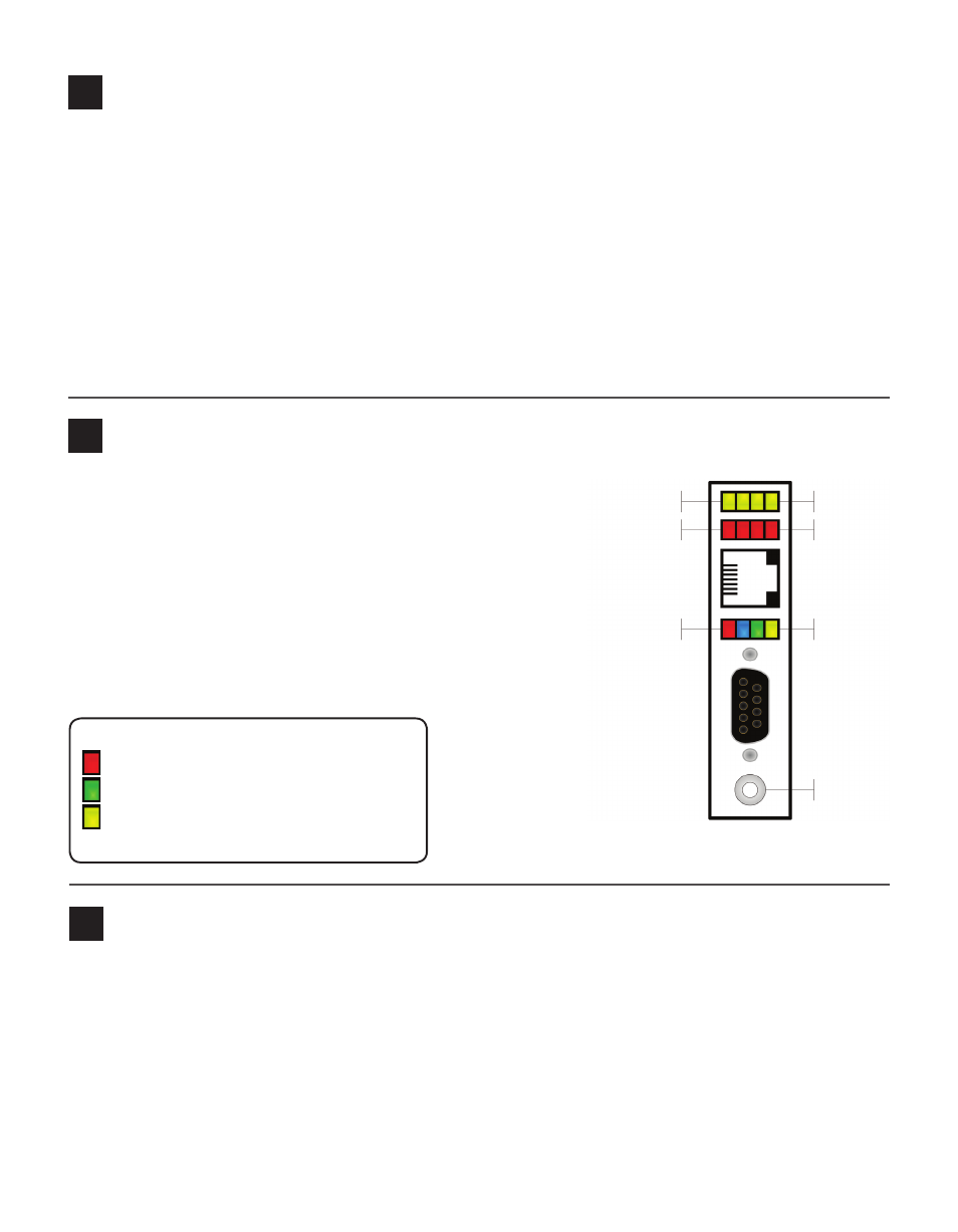
Use on-device configuration features
Next, use the device’s configuration features to make sure the
Click 513 is wired and working properly. The Click 513 has four
LEDs that monitor device activity and help you select tasks and
operating modes. It also has two banks of LEDs: one of yellow
LEDs that represent submenu 1 and one of red for submenu 2.
Check the LEDs to make sure the device has power.
The Click 513 also has a push-button, labeled Mode Switch,
used for selecting tasks and operating modes.
Yellow LEDs
Red LEDs
Multicolored LEDs
Button
Main Menu
Sub Menu 1
Sub Menu 2
5
How to use the push-button to navigate through mode and task menus
Select a task or operation function by navigating through the main menu (multicolored LEDs) and the sub-
menus (yellow and red LEDs) using the push-button as described below:
LED activity-indicating functions:
Red – Shows device has power
Green – Shows device is transmitting data
Yellow – Shows device is receiving data
The blue LED has no activity-indicating function
1 Enter the main menu and cycle through it by
holding the push-button down.
2 Release the push-button once the cycle reaches
the desired mode.
3 Press the push-button again to select the mode.
Once selected, the mode will either start running
or the first submenu (yellow LEDs) will start.
4 Hold the push-button to cycle through the first
submenu.
5 Release the push-button once the desired sub-
menu selection is displayed.
6 Press the push-button again to select the func-
tion. The function will now run.