Westermo TD-36 User Manual
Page 15
15
6618-2202
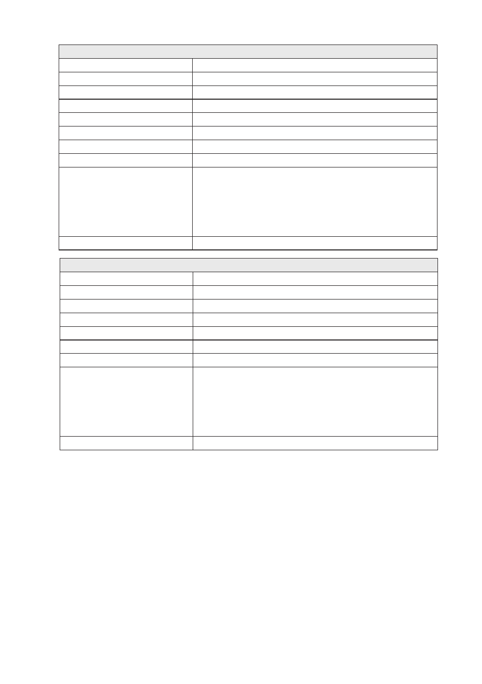
Generic I/O interface Input
Electrical specification
Opto isolated input
Input voltage range
0 – 60 VDC
Input current
5 mA @ 60 VDC
Input inactive
Uin < 2.5 V
Input active
Uin >5.0 V
Transmission range
Cable length ≤ 15 m
Connection
Detachable screw terminal (DCE )
Connector size
0.2 – 2.5 mm
2
(AWG 24 – 12)
Isolation to
Power port
3 kV
rms
50 Hz 1 min
PSTN line
2 kV
rms
50 Hz 1 min
Leased Line
2 kV
rms
50 Hz 1 min
RS-232
2 kV
rms
50 Hz 1 min
RS-485
2 kV
rms
50 Hz 1 min
I/O output
2 kV
rms
50 Hz 1 min
Shielded cable
Not required*
* Railway installation close to the rails.
For a cable located within 3 m and connected to this port, the use of shielded cable is recommended, this is
to minimise the risk of interference. The cable shield should be properly connected (360°) to an earthing point
within 1 m of this port. This earthing point should have a low impedance connection to the conductive enclo-
sure of the apparatus cabinet, or similar, where the unit is built-in. This conductive enclosure should be con-
nected to the earthing system of an installation and may be directly connected to the protective earth.
Generic I/O interface Relay Output
Electrical specification
One change over contact
Switching voltage
Max 40 V AC/DC
Switching current
Max 500 mA AC/DC
Electrical endurancee
5 x 10
5
operations at 20 W / 20 VA Resistive load
Transmission range
Cable length ≤ 15 m
Connection
Detachable screw terminal (DCE )
Connector size
0.2 – 2.5 mm
2
(AWG 24 – 12)
Isolation to
Power port
3 kV
rms
50 Hz 1 min
PSTN line
2 kV
rms
50 Hz 1 min
Leased Line
2 kV
rms
50 Hz 1 min
RS-232
1.5 kV
rms
50 Hz 1 min
RS-485
1.5 kV
rms
50 Hz 1 min
I/O input
2 kV
rms
50 Hz 1 min
Shielded cable
Not required*