Northfire 3400, 20 fan & valve wiring diagram/instructions – Archgard 3400-DVTR20N-2 User Manual
Page 20
Northfire 3400
20
FAN & VALVE WIRING DIAGRAM/INSTRUCTIONS
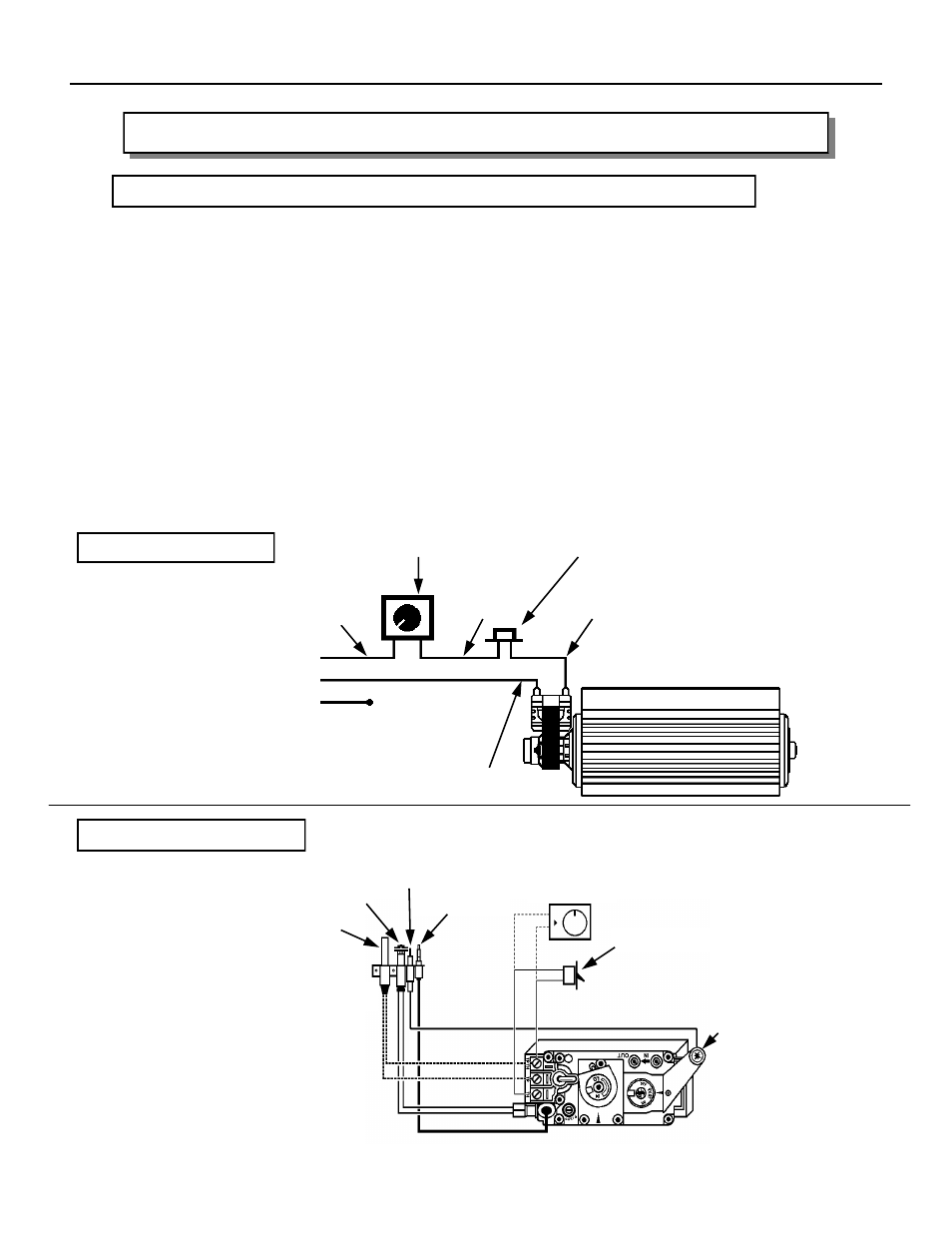
ELECTRICAL CONNECTIONS (for optional convection fan kit 999-DV-FK only)
Install the fan first. Remove the lower louvers and gently place the bottom front lip of the
blower mounting bracket into the opening. Slide the blower assembly into the bottom of the
fireplace. Rotate the blower into position. Be careful not to damage the fan blades. The fan
blades will now face towards you. Line up the holes on fan bracket to the mounting bracket at
the bottom of the fireplace. Place a screw at each of the three holes and tighten.
Run 120VAC power line through the left side of the fireplace and into the bottom of the gas
fireplace.
Be sure to connect a grounding wire to the side of gas fireplace. Use any screw hole on the
side for this purpose.
Slide the thermal snap switch into the fork like bracket underneath the left side of the firebox.
Neatly tie down and tuck the wires down at the bottom and to the back of the fireplace.
CAUTION: Do not allow any wires to touch the bottom of the firebox. Otherwise, the wires
will melt and short-out.
Screw the speed controller bracket to the bottom left sidewall of the gas fireplace.
VALVE CONNECTIONS
PILOT
REMOTE WALL
OPTIONAL
THERMOSTAT
THERMOPI
SPARK
THERMOCOUP
PILOT
SPARKE
WIRING DIAGRAM
SPEED CONTROL
LINE (BLACK)
CONVECTION BLOWER
GROUND (GREEN)
NEUTRAL
SIDE OF
120 VAC
BLACK
BLACK
WHITE
BLACK