5 rear panel, Model 4, Continued – ARM Electronics RT4CD User Manual
Page 12
1.5 REAR PANEL
1.5 REAR PANEL
Continued
Continued
…
…
Model 4
1)
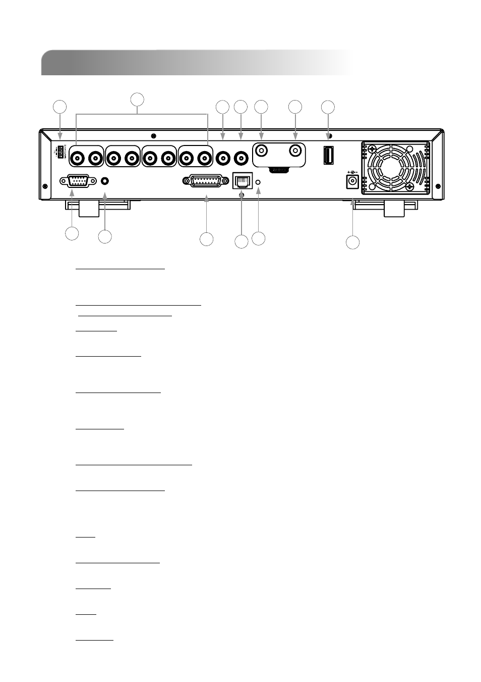
75Ω / HI-IMPEDANCE:
When using Loop function, please switch to HI-IMPEDANCE. When you don’t use Loop function,
please switch to 75Ω.
2)
VIDEO INPUT (CHANNEL 1 - 4): Connect to video sources, such as cameras.
LOOP (CHANNEL 1 - 4): Video output.
3)
MONITOR:
Connect to Main monitor.
4)
CALL MONITOR:
Connect to CALL monitor. Show the channel switch display. When the alarm is triggered, the
call monitor will show the image of the triggered channel for a period of time.
5)
AUDIO IN (1 audio-in):
Connect to audio sources, such as cameras equipped with the audio function.
When users start the recording function, the audio input will be recorded.
6)
AUDIO OUT:
Connect to a monitor or speaker.
With 1 mono audio output from the same source.
7)
D/V PORT (Digital Video Port):
Connect to a VGA converter.
8)
EXTERNAL I/O PORT:
Insert the supplied 15PIN DSUB to this port for connecting external devices (alarm input,
external alarm, PTZ camera).
For detailed I/O port PIN configuration, please refer to Appendix #2.
9)
LAN:
Connect to Internet by LAN cable.
10)
LINK / ACT LED light:
When the Internet is activated, the LED light will be on
11)
POWER:
Connect to the supplied adapter.
12)
USB:
Support USB flash drive firmware update and file backup.
13)
IR PORT:
Connect the IR receiver for remote control.
9
USB
INPUT
V
D /
1
LOOP
EXTERNAL I/O
INPUT
2
LOOP
LOOP
LOOP
3
INPUT
4
INPUT
ACT.
LINK
LAN
CALL
MONITOR
IN
OUT
DC 19V
IR
5
7
2
8
9
11
6
4
3
1
10
12
13