Rear connectors, Power connection, Usb connector – Ensemble Designs BrightEye 57 3G/HD/SD/Analog Test Signal and Sync Pulse Generator User Manual
Page 18: Audio out
www.ensembledesigns.com
BrightEye 57
TM
BrightEye 57
3G/HD/SD/Analog Test Signal and Sync Pulse Generator User Guide
Page 18
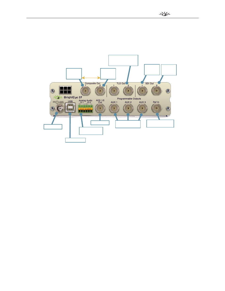
Rear Connectors
All connections to the BrightEye 57 are made on the rear of the unit. Refer to the illustration below.
SD Composite Outputs
capable of simultaneous
Bars and Black — even
when SDI Output is HD
3G / HD / SD SDI Outputs
available with either
capable of simultaneous
Bars and Black
Independent
Selection
TSG (if SD)
Bars
Black
TSG (if SD)
Bars
Black
Tri-Level Sync
available with either
HD or SD SDI Out
Programmable
Outputs
Power Input
Balanced Audio
Outputs
AES Output
Genlock Reference
Input
Choose:
AES Silence
AES Audio 1/2, 3/4,
5/6, 7/8, 9/10, 11/12,
13/14, 15/16
LTC (Timecode)
Word Clock
6 Hz Pulse
Comprehensive control
from PC or Mac
Accepts:
Analog Composite
TLS
10 MHz
Easily powered
from battery
or AC supply
USB Interface
TSG,
Color Bars
or Black
TSG,
Color Bars
or Black
Power Connection
Connect a modular power supply to the 12 volt DC power input connection on the far left of the unit.
Use the locking ring to secure it. Make sure you are using a power supply that provides at least 12V at
1.5A.
USB Connector
The USB connector is used to provide more comprehensive control, diagnostics, and upgrades to the
unit from a PC or Mac. Use the BrightEye Control application (version 2.1.2 or later) included on CD-
ROM to make adjustments as described in the Operation section of this user guide.
Audio Out
The Audio Out provides two channels of an analog audio reference tone. Wiring is done by inserting a
6 pin connector provided with the unit. Analog reference levels can be configured from the BrightEye
Control application.
To connect audio to this connector type, strip the audio wire to about 3/8” (8 mm). Solder tinning is
not required. Push the wire into the opening at the bottom of the connector to seat the connection.
This will snap the wire into place.
To remove the wire, push in the pin above the connection with a small pointed tool. This will release
the wire from the connector.