HEIDENHAIN TNC 407 (280 580) ISO Programming User Manual
Page 286
9-8
9
External Data Transfer
TNC 426/TNC 425/TNC 415 B/TNC 407
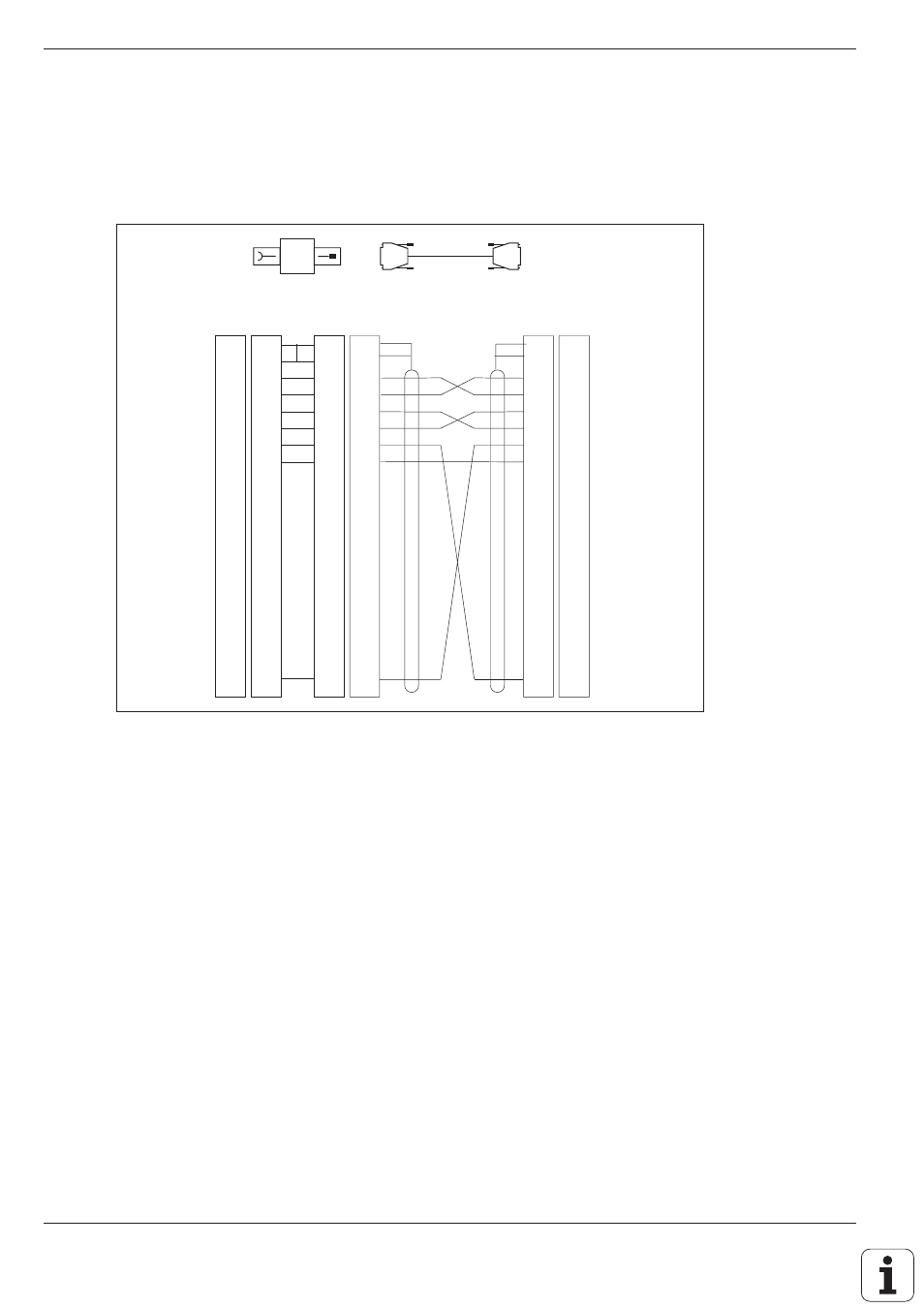
Fig. 9.3:
Connecting a non-HEIDENHAIN device to the RS-232-C/V.24 interface
ws/br
WH/BN
ws/br
WH/BN
GND Chassis
RXD
TXD
CTS
RTS
DTR
GND Signal
DSR
1
2
3
4
5
6
7
8
9
10
11
12
13
14
15
16
17
18
19
20
1
2
3
4
5
6
7
8
9
10
11
12
13
14
15
16
17
18
19
20
•
•
1
2
3
4
5
6
7
8
9
10
11
12
13
14
15
16
17
18
19
20
ge
gn
rs
gr
br
rt
bl
1
2
3
4
5
6
7
8
9
10
11
12
13
14
15
16
17
18
19
20
1
2
3
4
5
6
7
8
9
10
11
12
13
14
15
16
17
18
19
20
1
2
3
4
5
6
7
8
9
10
11
12
13
14
15
16
17
18
19
20
V.24-Adapter-Block
RS-232-C Adapter block
•
•
•
•
•
LE
Chassis GND
TXD
RXD
RTS
CTS
DSR
Signal GND
DTR
GN
YL
GY
PK
BL
RD
BN
Pin Layout and Connecting Cable for the Data Interfaces
Non-HEIDENHAIN devices
The connector pin layout on a non-HEIDENHAIN device may differ
considerably from that on a HEIDENHAIN device, and depends on the
unit and the type of data transfer. Fig. 9.3 shows the connector pin layout
on the adapter block.