Contour train (cycle 25), 25 contour train, 6 sl c y cles – HEIDENHAIN TNC 426 (280 476) User Manual
Page 322
HEIDENHAIN TNC 426, TNC 430
295
8.6 SL c
y
cles
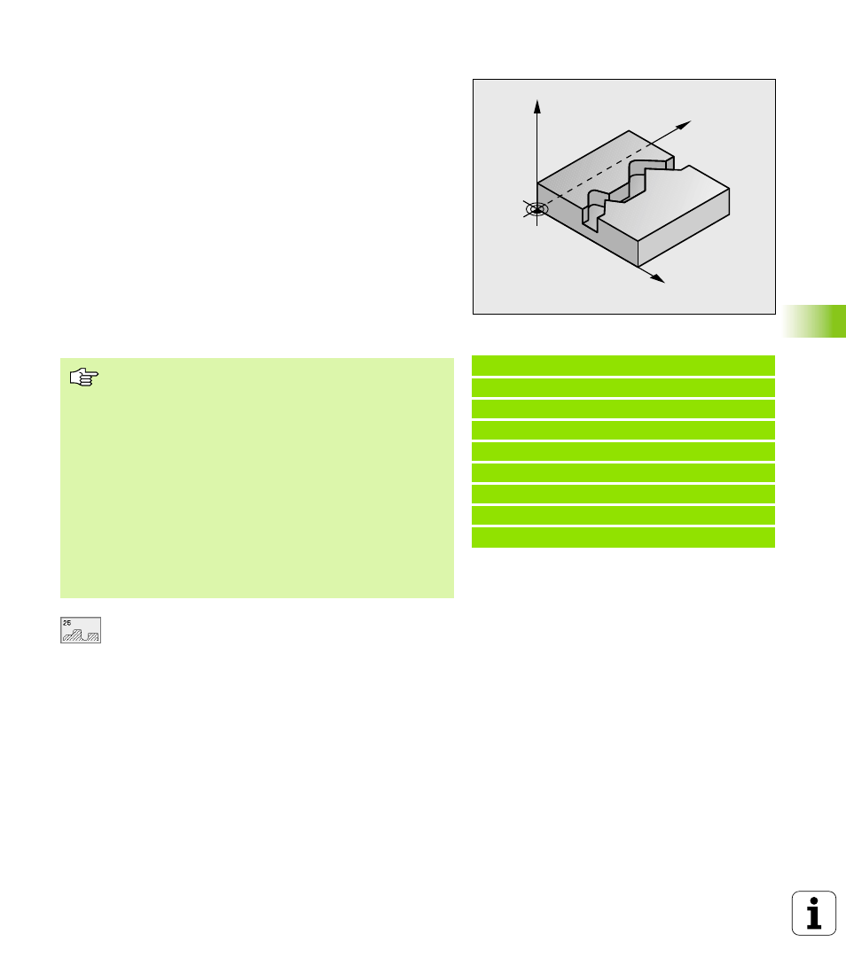
CONTOUR TRAIN (Cycle 25)
In conjunction with Cycle 14 CONTOUR GEOMETRY, this cycle
facilitates the machining of open contours (i.e. where the starting
point of the contour is not the same as its end point).
Cycle 25 CONTOUR TRAIN offers considerable advantages over
machining an open contour using positioning blocks:
n
The TNC monitors the operation to prevent undercuts and surface
blemishes. It is recommended that you run a graphic simulation of
the contour before execution.
n
If the radius of the selected tool is too large, the corners of the
contour may have to be reworked.
n
The contour can be machined throughout by up-cut or by climb
milling. The type of milling even remains effective when the
contours are mirrored.
n
The tool can traverse back and forth for milling in several infeeds:
This results in faster machining.
n
Allowance values can be entered in order to perform repeated
rough-milling and finish-milling operations.
7
7
7
7
Milling depth
Q1 (incremental value): Distance
between workpiece surface and contour floor
7
7
7
7
Finishing allowance for side
Q3 (incremental
value): Finishing allowance in the working plane
7
7
7
7
Workpiece surface coordinate
Q5 (absolute value):
Absolute coordinate of the workpiece surface
referenced to the workpiece datum
7
7
7
7
Clearance height
Q7 (absolute value): Absolute
height at which the tool cannot collide with the
workpiece. Position for tool retraction at the end of
the cycle.
7
7
7
7
Plunging depth
Q10 (incremental value): Dimension
by which the tool plunges in each infeed
7
7
7
7
Feed rate for plunging
Q11: Traversing speed of the
tool in the tool axis
Example: NC blocks
62 CYCL DEF 25.0 CONTOUR TRAIN
Q1=-20 ;MILLING DEPTH
Q3=+0 ;ALLOWANCE FOR SIDE
Q5=+0 ;WORKPIECE SURFACE COORD.
Q7=+50 ;CLEARANCE HEIGHT
Q10=+5 ;PLUNGING DEPTH
Q11=100 ;FEED RATE FOR PLUNGING
Q12=350 ;FEED RATE FOR MILLING
Q1=-1 ;CLIMB OR UP-CUT
Y
X
Z
Before programming, note the following:
The algebraic sign for the cycle parameter DEPTH
determines the working direction. If you program DEPTH
= 0, the cycle will not be executed.
The TNC takes only the first label of Cycle 14 CONTOUR
GEOMETRY into account.
The memory capacity for programming an SL cycle is
limited. For example, you can program up to 256 straight-
line blocks in one SL cycle.
Cycle 20 CONTOUR DATA is not required.
Positions that are programmed in incremental dimensions
immediately after Cycle 25 are referenced to the position
of the tool at the end of the cycle.