2 overview of the connection area, 1 view from below, 2 view from above – SMA SI-TB-BOX-10 User Manual
Page 32: Overview of the connection area, View from below, View from above
Advertising
6 Electrical Connection
SMA America, LLC
32
SI_TDBOX-IA-eng-IUS122211
Installation Manual
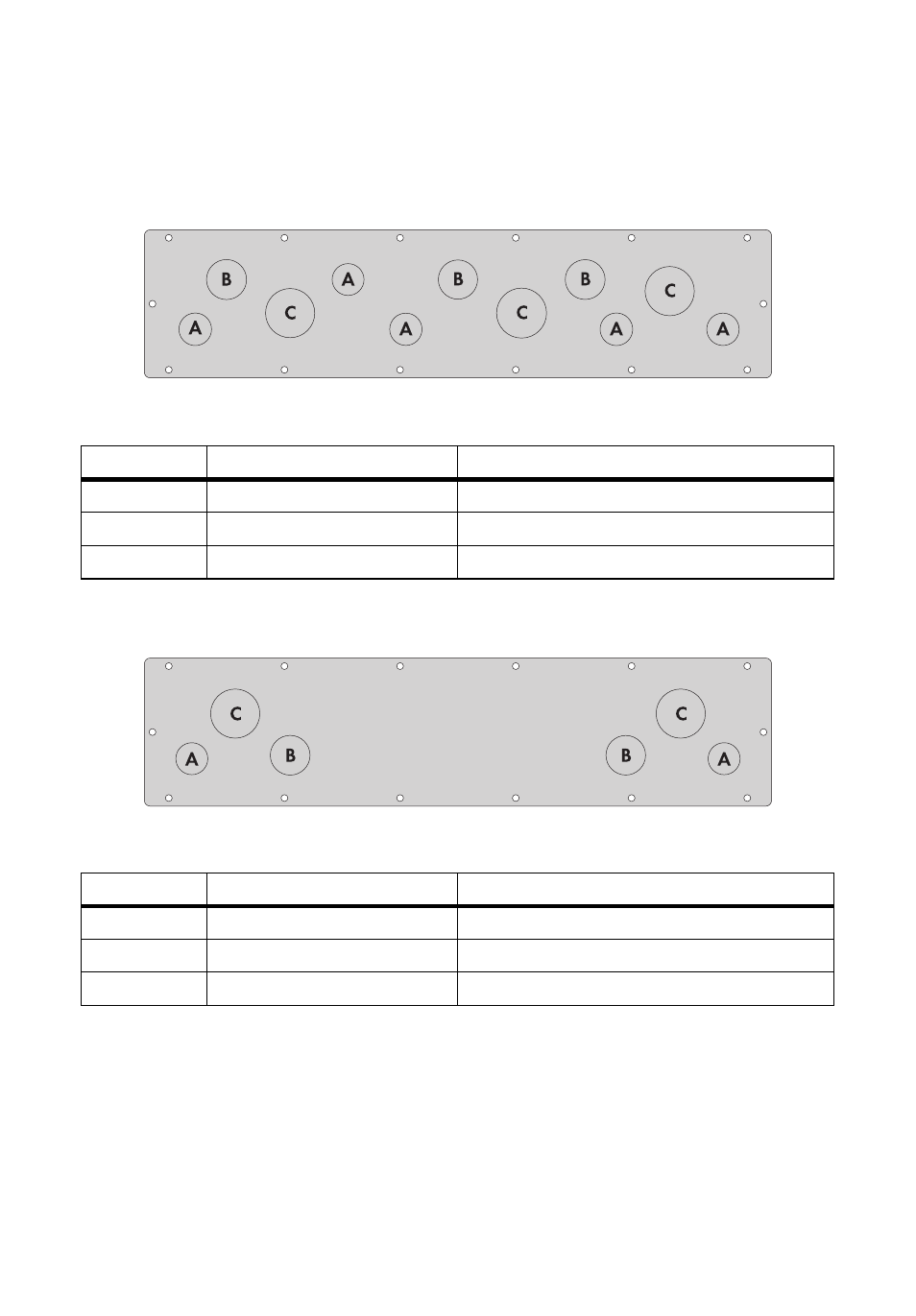
6.2 Overview of the Connection Area
6.2.1 View from Below
Figure 13: Flange plate with knockouts on the bottom of the Smartformer
6.2.2 View from Above
Figure 14: Flange plate with knockouts on the upper side of the Smartformer
Position
Description
Suitable conduit for connection (diameter)
A
Knockouts
3
⁄
4
in. (19 mm)
B
Knockouts
1 in. (25 mm)
C
Knockouts
1
1
⁄
4
in. (32 mm)
Position
Description
Suitable conduit for connection (diameter)
A
Knockouts
3
⁄
4
in. (19 mm)
B
Knockouts
1 in. (25 mm)
C
Knockouts
1
1
⁄
4
in. (32 mm)
Advertising