3 interior view, Interior view – SMA SI-TB-BOX-10 User Manual
Page 33
Advertising
SMA America, LLC
6 Electrical Connection
Installation Manual
SI_TDBOX-IA-eng-IUS122211
33
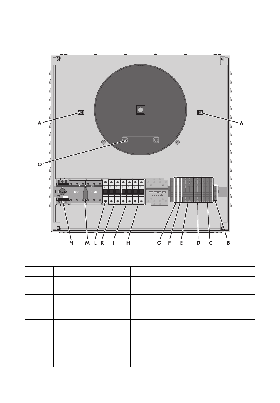
6.2.3 Interior View
Figure 15: Electrical connection area of the Smartformer
Position
Description
Color
Explanation
A
Cable clamps
‒
For clamping the cables when cables
are inserted via the upper flange plate.
B
Connecting terminal blocks
"Relay2: C", "Relay2: NC" with
spring clamp terminals
Black
For connecting the Sunny Island to the
load-shedding contactor in the
Smartformer
C
Connecting terminal blocks
"Grounding" with spring clamp
terminals
Yellow/
green
For connecting PE of the AC
sub-distribution for the loads, the
PV plant, the Sunny Island, and the
generator or the power distribution grid
and for grounding the protection against
contact
Advertising