SMA SI-TB-BOX-10 User Manual
Page 60
12 Troubleshooting
SMA America, LLC
60
SI_TDBOX-IA-eng-IUS122211
Installation Manual
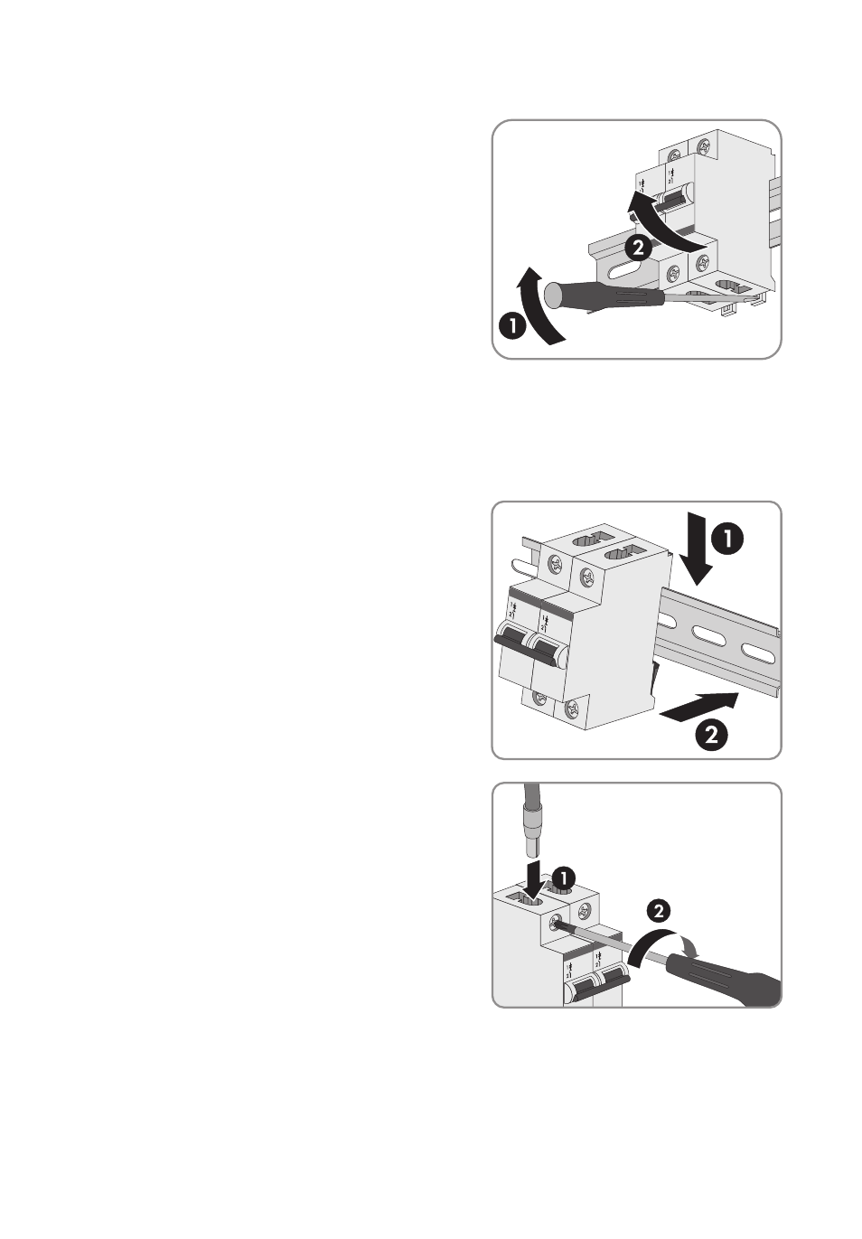
3. Use a screwdriver to release the locking lever of
each miniature circuit-breaker and lift the miniature
circuit-breaker off the top-hat rail.
4. Ensure that the fuse rating of the new miniature circuit-breaker matches the maximum feed
current of the PV plant of 25 A or 50 A.
5. Ensure that the miniature circuit-breaker is certified according to the specified UL standard and
adheres to the specified tripping characteristic (see Section 14 "Technical Data", page 64).
6. Position the new miniature circuit-breaker at the top
edge of the top-hat rail and press against the lower
edge of the top-hat rail until the locking lever
engages.
7. Insert the upper conductor into the upper screw
terminal and tighten screws (torque: 25 in-lbs.
(2.8 Nm)). Use a torque wrench with a
PZ 2 attachment or another suitable cross-head
screwdriver attachment.