4 installation, Installation – SMA String-Monitors Ethernet overvoltage protection set User Manual
Page 22
Advertising
Position
Quantity
Designation
C
1
RJ45 connector
D
1
Mounting tie
E
1
End clamp
F
1
Installation manual
4 Installation
4.1
Overview of the Connection Area of the SMA String-
Monitor
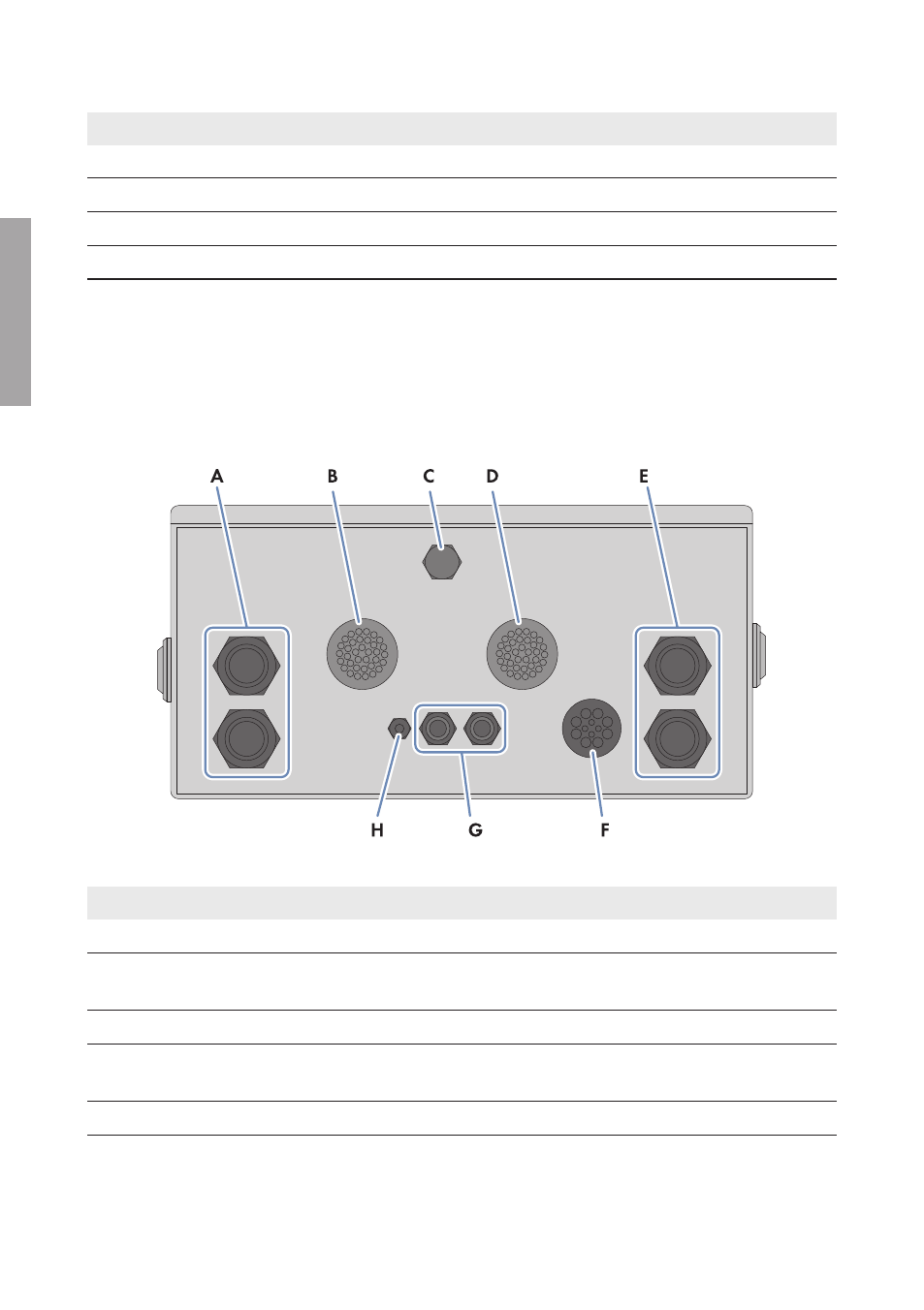
View from Below
Figure 5 : View of the SMA String-Monitor from below
Position
Designation
A
Enclosure opening with cable gland for the main cables DC+
B
Enclosure opening with string cable harness (PV+) and DC connectors (factory pre-
assembled)
C
Condensate drain
D
Enclosure opening with string cable harness (PV‒) and DC connectors (factory pre-
assembled)
E
Enclosure opening with cable gland for the main cables DC‒
4 Installation
SMA Solar Technology AG
Installation Manual
SSMAbleitKomm-IA-xx-10
22
ENGLISH
Advertising