SMA String-Monitors Ethernet overvoltage protection set User Manual
Page 27
• Mount the overvoltage protection unit on the top-hat rail. Observe the indicated mounting
position (see Section 4.2, page 24). The terminal EQUIP must point to the left.
• Fasten the end clamp immediately above or below the overvoltage protection unit on the
top-hat rail.
☑ The end clamp snaps into place and the overvoltage protection unit is fixed in
position on the top-hat rail.
6. To connect the overvoltage protection unit to the communication output:
• Plug the RJ45 connector on the supplied Ethernet cable into the EQUIP terminal of the
overvoltage protection unit.
• Connect the other end of the Ethernet cable to the String-Monitor Unit at terminal X7 in
accordance with the circuit diagram. Observe the prescribed cable route (see
Section 4.2, page 24).
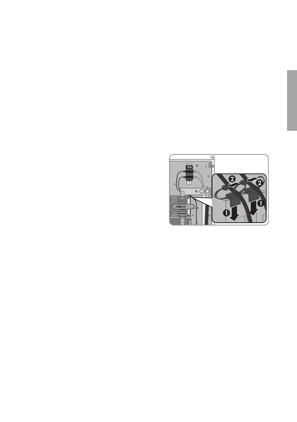
• Attach the Ethernet cable in the SMA String-Monitor with the cable brackets (see
• Push the mounting tie onto the bracket of
the DC load-break switch and secure the
Ethernet cable in position with the cable tie.
• Route the Ethernet cable for the communication output through the corresponding
enclosure opening (see Section 4.1, page 22) into the SMA String-Monitor. To do this,
pierce the membrane and push the Ethernet cable through the membrane.
• Connect the RJ45 connector to the inserted end of the Ethernet cable in accordance with
EIA/TIA 568B (eight-conductor) (see manual of RJ45 connector). Make sure that no
pieces of cable are dropped into the SMA String-Monitor.
• Route the Ethernet cable to the overvoltage protection unit in the cable channel according
to the cable route (see Section 4.2, page 24). To do this, remove the cover of the cable
channel, lay the Ethernet cable inside and replace the cover.
• Plug the RJ45 connector into the overvoltage protection unit at the terminal LINE IN.
• To connect the Ethernet cable to the next SMA String-Monitor in the communication bus,
plug the other end of the Ethernet cable into the overvoltage protection unit for the
communication input in the next SMA String-Monitor at the terminal LINE IN.
• To connect the Ethernet cable in the inverter, see inverter manual.
7. To connect the overvoltage protection unit to the communication input:
• Plug the RJ45 connector on the supplied Ethernet cable into the EQUIP terminal of the
overvoltage protection unit.
4 Installation
SMA Solar Technology AG
Installation Manual
27
SSMAbleitKomm-IA-xx-10
ENGLISH