SMA String-Monitors Ethernet overvoltage protection set User Manual
Page 26
☐ Cable type: at least Cat5 with shielding S-UTP, F-UTP or higher
☐ Maximum cable length: 100 m
☐ The RJ45 connectors must be connected in accordance with EIA/TIA 568B (eight-conductor):
Signal
Terminal
X7 and X9
EIA/TIA 568B (eight-con-
ductor)
Insulated conductor color
TX+
1
(white/orange)
White/orange
TX-
2
(orange/white or orange)
Orange/white or orange
RX+
3
(white/green)
White/green
Not assigned
4
(blue/white or blue)
Blue/white or blue
Not assigned
5
(white/blue)
White/blue
RX-
6
(green/white or green)
Green/white or green
Not assigned
7
(white/brown)
White/brown
Not assigned
8
(brown/white or brown)
Brown/white or brown
Procedure:
1. Disconnect the inverter on the DC side (see inverter manual).
2. Disconnect the SMA String-Monitor (see SMA String Monitor manual).
3. Disassemble the protective covers of the SMA String-Monitor (see SMA String-Monitor
manual).
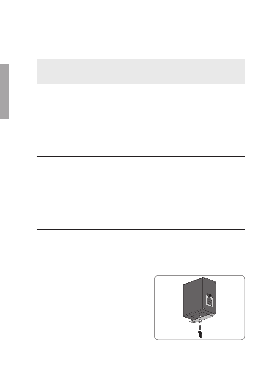
4. At the bottom of the overvoltage protection unit,
attach the top-hat rail support with washer and
screw. The bracket of the top-hat rail support
must point to the side of the overvoltage
protection unit with the inscription EQUIP.
5. Install one overvoltage protection unit for each communication output and (where necessary)
communication input as follows:
4 Installation
SMA Solar Technology AG
Installation Manual
SSMAbleitKomm-IA-xx-10
26
ENGLISH