SMA String-Monitors Ethernet overvoltage protection set User Manual
Page 28
• Connect the other end of the Ethernet cable to the String-Monitor Unit at terminal X9
according to the circuit diagram. Observe the prescribed cable route (see Section 4.2,
page 24).
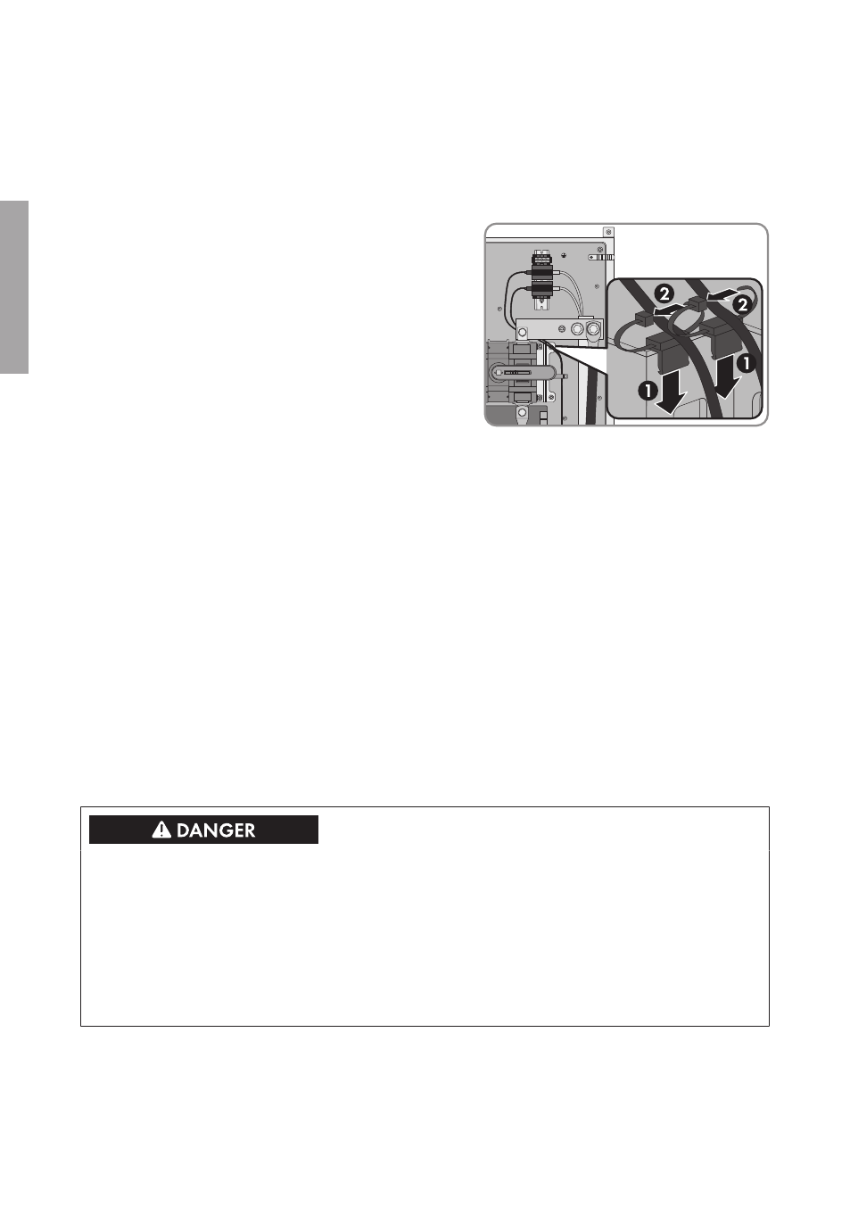
• Attach the Ethernet cable in the SMA String-Monitor with the cable brackets (see
• Push the mounting tie onto the bracket of
the DC load-break switch and secure the
Ethernet cable in position with the cable tie.
• Route the Ethernet cable for the communication input through the corresponding
enclosure opening (see Section 4.1, page 22) into the SMA String-Monitor. To do this,
pierce the membrane and push the Ethernet cable through the membrane.
• Connect the RJ45 connector to the inserted end of the Ethernet cable in accordance with
EIA/TIA 568B (eight-conductor) (see manual of RJ45 connector). Make sure that no
pieces of cable are dropped into the SMA String-Monitor.
• Route the Ethernet cable to the overvoltage protection unit in the cable channel according
to the cable route (see Section 4.2, page 24). To do this, remove the cover of the cable
channel, lay the Ethernet cable inside and reattach the cover.
• Plug the RJ45 connector into the overvoltage protection unit at the terminal LINE IN.
8. Remount the protective covers of the SMA String-Monitor (see SMA String-Monitor manual).
9. Switch the SMA String-Monitor back on (see SMA String Monitor manual).
5 Replacing the Overvoltage Protection Unit for Ethernet
Communication
Danger to life from electric shock due to live voltage
High voltages are present in the live components of the DC sub-distribution. Touching live
components results in death or serious injury due to electric shock.
• Disconnect the inverter on the DC side (see the inverter manual).
• Disconnect the DC sub-distribution (see the DC sub-distribution manual).
• Disconnect all DC sub-distributions that are connected in parallel in the DC connection area
(see the manual of the respective DC sub-distribution).
Additionally required material (not included in the scope of delivery):
☐ One or two overvoltage protection units, depending on the number of units to be replaced (for
SMA order number see SMA String-Monitor manual)
5 Replacing the Overvoltage Protection Unit for Ethernet Communication
SMA Solar Technology AG
Installation Manual
SSMAbleitKomm-IA-xx-10
28
ENGLISH