3 connecting additional grounding, Connecting additional grounding – SMA SB 1300TL User Manual
Page 27
• Insert N (or respectively L2 in case of split phase) into screw terminal 1 on the bush insert
and tighten the screw.
• Insert L (or respectively L1 in case of split phase) into screw terminal 2 on the bush insert
and tighten the screw.
10. Ensure that all conductors are securely in place in the bush insert.
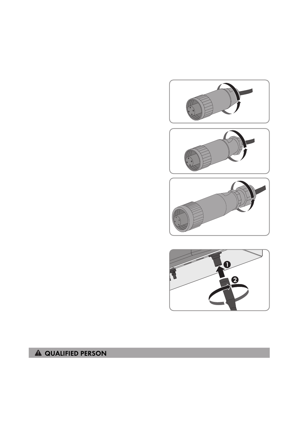
11. Screw the threaded sleeve tightly onto the bush
insert.
12. When using pressure screw, fastening case and
sealing ring, screw the pressure screw firmly
onto the threaded sleeve. The fastening case will
be pressed into the threaded sleeve and no
longer be visible.
13. When using the cable gland, screw the cable
gland firmly onto the threaded sleeve.
☑ The AC connection socket is mounted.
14. Insert the AC connection socket into the AC pin
connector on the inverter. Remove the protective
cap from the AC pin connector beforehand, if
required.
15. If the AC connection socket is not to be connected to the inverter immediately, close the AC
pin connector on the inverter with the protective cap provided.
6.3.3
Connecting Additional Grounding
If additional grounding or equipotential bonding is required locally, you can connect additional
grounding to the inverter. This prevents touch current if the grounding conductor at the connecting
terminal plate for the AC cable fails. The required clamping bracket, the screw and the conical
spring washer are part of the scope of delivery of the inverter.
6 Electrical Connection
SMA Solar Technology AG
Operating Manual
27
SB13-21TL-BE-en-11