SMA SB 1300TL User Manual
Page 30
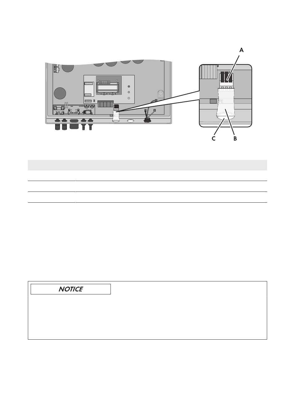
Overview of the connection area:
Figure 10: Fault indicator relay inside the inverter
Position
Designation
A
Terminals of the fault indicator relay
B
Cable route
C
Enclosure opening with filler plug
Requirement:
☐ The technical requirements of the fault indicator relay must be complied with (see Section 11
Cable requirements:
☐ The cable must be double-insulated.
☐ External diameter: 5 mm to 12 mm
☐ Conductor cross-section: 0.08 mm² to 2.5 mm²
☐ The cable type and cable-laying method must be appropriate for the application and location.
Destruction of the fault indicator relay as a result of contact overload
• Observe the maximum switching voltage and maximum switching current (see Section 11
• When connecting the fault indicator relay to the utility grid, protect it with an individual
circuit breaker.
6 Electrical Connection
SMA Solar Technology AG
Operating Manual
SB13-21TL-BE-en-11
30