External terminal functions – Yaskawa AO-12B2 User Manual
Page 10
Page 10
VS-616/676 Series Option Instruction Manual: Isolated Analog Monitor Card AO-12B2
* Default is 4-20mA setting.
EXTERNAL TERMINAL FUNCTIONS
AO-12B2 Monitor Card has three (3) output terminals for connection to peripheral equipment.
*
The signal monitored on TB1-1 or TB2-1 can be selected by setting the inverter’s program param-
eters. For details, refer to the specific “PROGRAMMING SETTINGS” tables.
•
Output analog signal levels of TB1-1 or TB1-2 can be adjusted by setting the inverter program
parameters. For details, refer to “OUTPUT SIGNAL LEVEL SETTING”.
•
When AO-12B2 is mounted on VS-616G3 or VS-616H3, the output signal level varies 0 to
+10 volts. In this case, negative polarity (0 to -10) cannot be output.
•
Output signal level can be adjusted to a maximum of 10 volts by setting program constants.
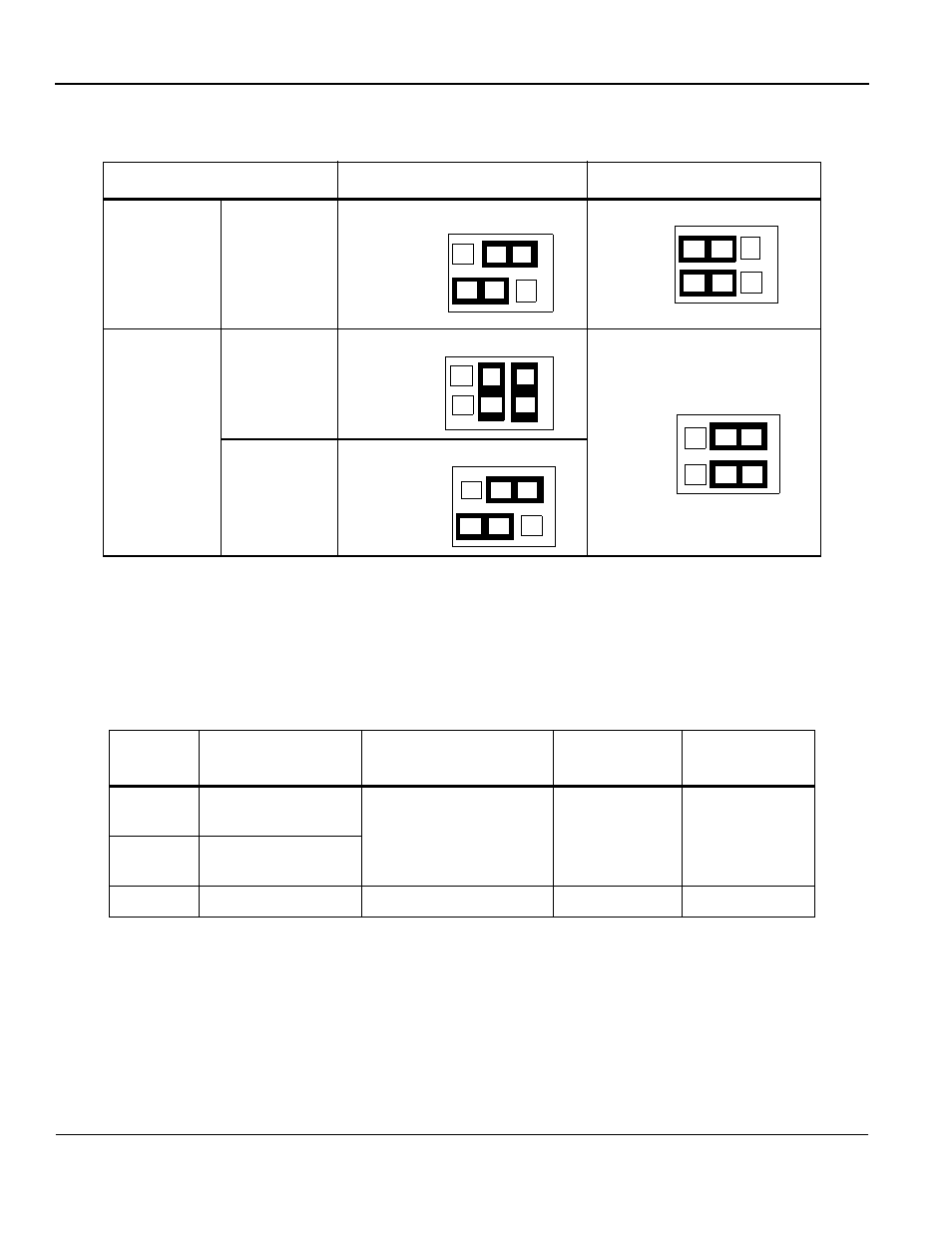
Table 5: Channel Two Jumper Selections
Signal Level
HDR3 Jumper Positions
HDR1 Jumper Positions
Voltage
(-10 to 10)
Current
0-20mA
4-20mA*
Table 6: Terminal Functions
Terminal
Symbol
Function
Signal Level
Output
Accuracy
Remarks
TB1-1
Analog signal
output: channel 1*
Selectable by jumpers
-10+10 VDC
0-20mA
4-20mA
Refer to the
following
programming
setting tables
Output
resolution:
11 bits +SIGN
(1/2048)
TB1-2
Analog signal
output: channel 2*
TB1-3
Common terminal
0 volts
--
--
1 to 3
HDR
3
2 4 6
1 3 5
4 to 6
1 to 3
HD
R
1
1 3 5
2 4 6
2 to 4
3 to 4
5 to 6
HD
R3
1 3 5
2 4 6
HDR1
2 4 6
1 3 5
4 to 6
3 to 5
4 to 6
1 to 3
HD
R
3
1 3 5
2 4 6