Yaskawa AO-12B2 User Manual
Page 13
VS-616/676 Series Option Instruction Manual: Isolated Analog Monitor Card AO-12B2
Page 13
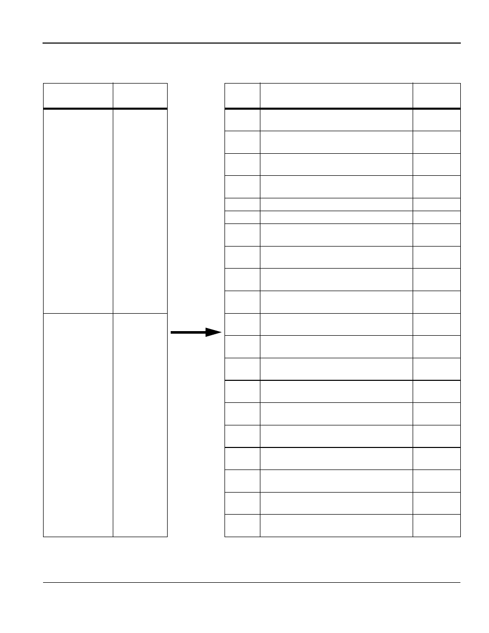
Table 9: Programming Settings With VS-616G5
Terminal
Program
Constant No.
Set
Value
Output
Content
Output
Accuracy
TB1-1
Channel 1
F4-01
01
Frequency reference
10V/max. output frequency
0.2%
02
Output frequency
10V/max. output frequency
0.2%
03
Output current
10V/inverter rated current
3%
05
Motor speed
10V/max. output frequency
0.2%
06
Output voltage 10V/200V or 400V
3%
07
DC bus voltage 10V/400V or 800V
3%
08
Output power
10V/inverter capacity (kW)
5%
09
Torque reference (internal)
10V/motor rated torque
5%
15
Terminal 13 input voltage
10V/10V or 20ma
0.2%
16
Terminal 14 input voltage
10V/10V or 20mA
0.2%
TB1-2
Channel 2
F4-03
17
Terminal 16 input voltage
10V/10V or 20ma
0.2%
18
Motor secondary current (Iq)
10V/motor rated primary current
5%
19
Motor exciting current (Id)
10V/motor rated primary current
5%
20
Output frequency after soft-start
10V/max. output frequency
0.2%
21
ASR input
10V/max. output frequency
0.2%
22
ASR output
10V/motor rated primary current
5%
23
Speed deviation
10V/max. output frequency
0.2%
24
PID feedback amount
10V/max. output frequency
0.2%
26
Output Voltage Referenced (Vg)
10V/200V or 400V
0.2%
27
Output Voltage Referenced (Vd)
10V/200V or 400V
0.2%