Output signal level setting – Yaskawa AO-12B2 User Manual
Page 15
VS-616/676 Series Option Instruction Manual: Isolated Analog Monitor Card AO-12B2
Page 15
OUTPUT SIGNAL LEVEL SETTING
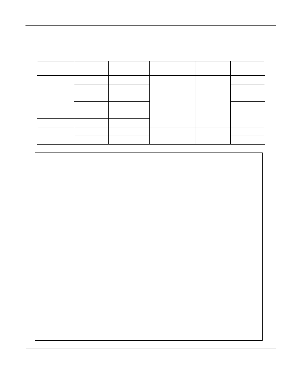
Output signal level of external terminal TB1-1 or TB1-2 can be set by programming the appropriate
parameter to a value as indicated by 10 volts (or 4-20mA) x setting value /100%.
Applicable
Inverter
External
Terminal
Program
Constant No.
Setting
Range
Setting
Unit
Initial
Value
VS-616G3
TB1-1
bn-11
0.00 to 2.55
0.01
1.00
TB1-2
bn-12
0.50
VS-616H3
TB1-1
bn-16
0.000 to 10.000
0.001
1.000
TB1-2
bn-18
0.500
VS-676VG3
TB1-1
bn-23
0.000 to 10.000
0.001
1.000
VS-676VH3
TB1-2
bn-25
VS-616G5
TB1-1
F4-02
0.00 to 2.50
0.01
1.00
TB1-2
F4-04
0.50
Programming Example:
Program a G5 inverter to output a signal on Channel 2 of the AO-12B2
Option Card proportional to output current. The desired signal level is
10 volts at 200% of inverter rated output current.
Step 1. Verify that the option card is properly installed and wired.
Step 2. Jumper Settings:
Channel 2 as output voltage -10 to +10 VDC
HDR1 Jumpers in position 2 to 4 and 1 to 3
HDR3 Jumpers in position 4 to 6 and 1 to 3
Refer to Pages 9 and 10 for further details.
Step 3. Program Channel 2 to desired signal.
Output current = > F4-03=03
Refer to Table 9 on Page 14.
Step 4. Program desired signal amplitude.
If voltage desired is 10V @ 200% current,
this means 5V @ 100% current.
Thus, a setting value of 50% or 0.50 is necessary, F4-04 = 0.50
Step 5. Verify operation.
So, 10V
X
Setting Value = 5V
100%