Jumper selection – Yaskawa AO-12B2 User Manual
Page 9
VS-616/676 Series Option Instruction Manual: Isolated Analog Monitor Card AO-12B2
Page 9
JUMPER SELECTION
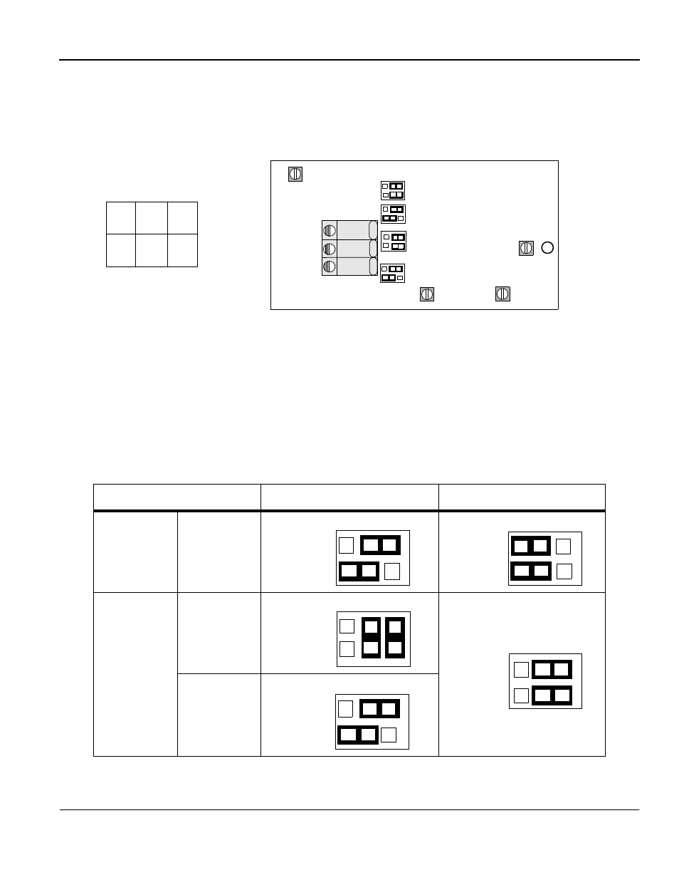
Figure 6 shows the AO-12B2 Option Card’s terminal block and jumper locations.
The pin arrangement is also shown. Refer to Tables 4 & 5 for jumper configuration details.
* Default is 4-20mA setting.
Table 4: Channel One Jumper Selections
Signal Level
HDR4 Jumper Positions
HDR2 Jumper Positions
Voltage
(-10 to 10)
Current
0-20mA
4-20mA*
1
2
3
VR1
HDR2
HDR1
TB1
HDR3
HDR4
VR4
VR3
VR2
Header Pin
Layout
1 3 5
2 4 6
HDR*
Notes:
1. Jumpers HDR2 and HDR4 setup Terminal 1.
2. Jumpers HDR1 and HDR3 setup Terminal 2.
Fig. 6 Isolated Analog Monitor Card Header Layout Locations
4 to 6
HDR4
4 6
1 to 3
2
1
3
5
2 to 4
1 to 3
HDR2
2 4
6
1 3 5
3 to 4
5 to 6
HDR4
2 4 6
1 3 5
4 to 6
3 to 5
HDR
2
2 4 6
1 3 5
1 to 3
HDR
4
1 3 5
2 4 6
4 to 6